Data centers are, at their core, heat management problems. The computing infrastructure inside them generates enormous quantities of heat that must be removed continuously and reliably. The consequences of getting the cooling design wrong range from efficiency losses and premature hardware failures at the mild end to catastrophic thermal events and unplanned downtime at the severe end. As rack densities climb with the adoption of GPU-heavy AI workloads and high-performance computing configurations, the thermal management challenge has become considerably more demanding than it was even five years ago.
Computational fluid dynamics (CFD) analysis has become a central tool in data center cooling design precisely because the airflow and heat transfer behavior inside a live data center is too complex to characterize adequately through simplified hand calculations or rule-of-thumb guidelines. The interactions between raised floor plenum pressure, hot aisle and cold aisle containment, rack exhaust temperatures, and CRAC or CRAH unit placement create a three-dimensional flow field that intuition and experience alone cannot reliably predict. CFD makes that flow field visible before a single piece of equipment is installed.
What CFD Actually Models in a Data Center Environment
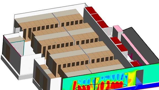
A CFD simulation of a data center solves the governing equations of fluid flow and heat transfer across a computational mesh representing the physical space. In practical terms, this means the model captures how cold supply air travels from the cooling unit discharge through the cold aisle, enters equipment intakes, absorbs heat from servers and networking hardware, exits through hot aisle exhausts, and returns to the cooling units for recirculation.
The inputs to a well-constructed model include room geometry, floor tile perforation patterns and their discharge coefficients, rack layout and orientation, rack-level heat load distribution, cooling unit capacities and supply temperatures, and any containment structures present. The outputs include three-dimensional temperature and velocity fields throughout the space, hot spot identification at the rack and row level, recirculation patterns where hot exhaust air bypasses containment and contaminates cold supply air, and underfloor plenum pressure distribution in raised floor configurations.
Modern CFD tools used in data center applications, including 6SigmaDCX from Future Facilities, FloTHERM XT from Mentor, and Ansys Icepak, include validated models for standard data center equipment and allow engineers to import rack configurations directly from vendor specifications. This capability significantly reduces model build time and improves the fidelity of results compared to generic block representations of IT equipment.
The level of detail in a data center CFD model can be scaled to the purpose. A room-level model optimized for airflow visualization and hot spot identification requires less computational resource than a detailed rack-level model resolving individual server blade airflow paths. In practice, engineers often build models at multiple scales: room-level for overall flow architecture validation, then higher-fidelity local models for specific areas of concern identified in the broader simulation.
Where CFD Adds the Most Value in the Design Process
The leverage points for CFD analysis in data center design are concentrated in three phases: initial layout optimization, cooling system sizing, and capacity planning for future growth.
During initial layout, CFD allows designers to evaluate multiple floor plan configurations, containment arrangements, and cooling unit placements before committing to installation. The difference in thermal performance between an optimized layout and a reasonable but unanalyzed one can be substantial. Recirculation zones, where hot exhaust air finds pathways back into equipment intakes, are common in poorly planned layouts and can drive equipment inlet temperatures 10 to 15 degrees Celsius above supply air temperature even when overall cooling capacity appears adequate. CFD identifies these zones explicitly, allowing the layout to be adjusted at the design stage where changes cost nothing beyond engineering time.
Cooling system sizing is an area where CFD provides value that conventional load calculations cannot match. A cooling capacity calculation based on total IT load determines how much heat needs to be removed; it says nothing about where that heat is distributed, whether the airflow delivery matches the spatial distribution of the load, or whether localized high-density racks will be adequately served by the proposed system. CFD models the spatial reality of the airflow delivery and heat load simultaneously, exposing mismatches between cooling supply and demand that aggregate calculations miss entirely.
Capacity planning uses CFD to evaluate the thermal implications of adding equipment or increasing rack densities before changes are made to the live environment. A data center operating comfortably at current loads may have significant thermal constraints that only become apparent when density increases. Running a CFD simulation with the proposed future state identifies those constraints in advance, informing decisions about whether additional cooling capacity is needed, whether containment modifications would resolve the issue, or whether the proposed changes need to be redistributed across the floor plan.
Airflow Efficiency and the PUE Connection
Power usage effectiveness (PUE) has become the standard efficiency metric for data center operations, and airflow management has a direct and substantial impact on achievable PUE values. A facility where cold supply air bypasses IT equipment and returns to cooling units without absorbing heat is running those units harder than necessary to compensate for the inefficiency. Hot air recirculation forces equipment fans to work at higher speeds to maintain acceptable component temperatures, increasing IT load slightly but more importantly driving up cooling unit energy consumption as supply temperatures are reduced to compensate.
CFD analysis quantifies these inefficiencies in a way that is difficult to achieve through operational measurement alone. A simulation can calculate the fraction of supply air that reaches IT equipment intakes versus the fraction that bypasses directly to cooling unit returns, a parameter sometimes called capture index or cooling effectiveness. Facilities consistently scoring low on this metric are strong candidates for containment improvements or airflow management modifications that can meaningfully reduce cooling energy consumption without any change to IT infrastructure.
The relationship between supply air temperature and PUE is another area where CFD informs operational decisions. ASHRAE thermal guidelines for data centers, particularly the A1 through A4 equipment classes, have progressively expanded the allowable inlet temperature range for IT equipment. Raising supply air temperature by several degrees Celsius reduces cooling unit compressor energy consumption significantly. CFD analysis validates whether a proposed supply temperature increase will maintain acceptable equipment inlet temperatures across all racks in the facility, supporting the operational decision with thermal data rather than relying on a conservative temperature margin that wastes energy.
High-Density Racks and the Shift to Liquid Cooling
The move toward AI training workloads and high-performance computing has pushed rack densities well beyond what conventional air cooling can serve reliably. Racks drawing 30, 50, or even 120 kW are increasingly common in specialized facilities, compared to the 5 to 10 kW average rack density of general enterprise data centers a decade ago. At those power levels, the volumetric airflow rates needed to maintain acceptable equipment temperatures become physically impractical to deliver through raised floor or overhead air distribution systems.
Direct-to-chip liquid cooling addresses this gap by routing coolant directly to cold plates mounted on processors, removing heat at the source rather than relying on airflow to carry it away from the equipment. Two-phase direct-to-chip (2PD2C) systems take this further: a dielectric fluid circulates to the cold plates, absorbs heat and vaporizes, then condenses back into liquid in a closed loop. The heat dissipation capacity of this approach substantially exceeds what single-phase water cooling achieves, with the added advantage of eliminating water from direct contact with electronic components.
The fluid distribution architecture in these systems depends heavily on the tubing that routes coolant between the coolant distribution unit (CDU), the manifolds, and the individual server cold plates. For data center cooling applications using stainless steel tubing in direct-to-chip loops, material selection and tube geometry directly affect pressure drop, thermal efficiency, and long-term system reliability. Smooth-bore 316L stainless steel tubing is well suited to these environments: its corrosion resistance holds up against both water-based coolants and dielectric fluids, its smooth interior surface minimizes friction losses along the coolant circuit, and its dimensional stability under pressure and thermal cycling maintains connection integrity across the service life of the installation.
CFD plays a specific and valuable role in designing these liquid cooling circuits. Pressure drop modeling through the tubing network, flow distribution across parallel cold plate circuits, and thermal performance validation under varying load conditions are all analyses that CFD handles with a level of detail that simplified network models cannot match. In hybrid environments where liquid-cooled racks sit alongside air-cooled equipment, CFD also captures the thermal interaction between the two systems, ensuring that the heat rejected by air-cooled equipment doesn’t compromise the inlet conditions of adjacent liquid-cooled racks or vice versa.
CFD as an Ongoing Operational Tool
The value of CFD analysis doesn’t end at the completion of initial design. Data centers are dynamic environments where IT loads shift, equipment is added or decommissioned, and cooling infrastructure ages or is upgraded. Maintaining a live CFD model calibrated against operational sensor data creates a digital twin of the facility’s thermal behavior that supports ongoing operational decisions.
Calibration against operational data is a critical step that distinguishes a useful operational model from a design model that has drifted from reality. Temperature sensors at equipment intakes and exhausts, airflow measurements at CRAC units and floor tiles, and rack-level power metering all provide data points for comparison against CFD predictions. Where discrepancies exist, they reveal either changes in the physical environment (tiles moved, blanking panels missing, equipment layouts changed) or model assumptions that need updating. A well-maintained calibrated model is considerably more useful for operational decision support than one built at design time and never revisited.
The data also supports proactive capacity management. A CFD model updated to reflect the current state of the facility can be used to run what-if scenarios: what happens to thermal conditions if a row of high-density GPU racks is added to the northwest quadrant? Does the existing cooling infrastructure handle it, or does the simulation reveal a hot spot developing at the row ends? Those questions are far less expensive to answer in simulation than through a live deployment that reveals problems after the equipment is already installed.
Limitations Worth Acknowledging
CFD analysis is a powerful tool, but its output quality depends directly on the quality of the inputs and the skill of the engineer interpreting the results. A model built with inaccurate heat load data, poorly characterized equipment airflow curves, or simplified representations of complex physical features will produce results that look precise but may not reflect reality accurately.
Validation against measured data is the most reliable check on model accuracy. Before relying on CFD predictions to make significant design or operational decisions, comparing simulation outputs against thermocouple measurements, anemometer readings, or smoke visualization in a representative portion of the facility builds confidence in the model’s fidelity.
Turbulence modeling choices, mesh resolution in regions of complex flow, and the representation of equipment airflow behavior all introduce uncertainty that experienced CFD engineers manage through sensitivity analysis and conservative interpretation of results. Understanding the limits of confidence in a simulation is as important as generating the simulation itself.
None of those limitations diminish the fundamental value of CFD in data center design. They simply mean that reliable results require treating it as an engineering discipline rather than a software product that produces answers automatically. Applied correctly, it remains the most effective tool available for understanding and optimizing the thermal behavior of complex data center environments before, during, and after construction.