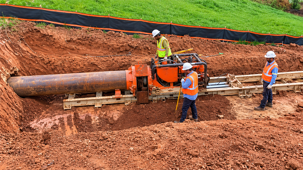
Horizontal Directional Drilling (HDD) is a trenchless construction method used to install underground pipelines and utility conduits with minimal surface excavation. The technique allows pipes to be installed beneath roads, highways, railway tracks, rivers, buildings and other obstacles without opening a continuous trench along the entire alignment. It is widely used for water supply pipelines, sewer networks, gas distribution, power cables, telecommunications ducts and other underground utility infrastructure.
Unlike conventional open-cut installation, which requires excavation along the pipe route, HDD uses a steerable drilling system to create an underground bore along a planned alignment. The bore is then enlarged to accommodate the required pipe diameter, and the pipe is pulled through the prepared borehole. This approach can reduce disruption to traffic, limit damage to existing surfaces and help maintain access to surrounding properties during construction.
HDD is particularly suitable for urban infrastructure projects where underground utilities must cross busy roads, railway corridors, waterways or environmentally sensitive areas. However, successful installation depends on ground investigation, accurate alignment planning, drilling fluid management, bore stability, equipment selection and careful control of pipe pulling forces.
Advantages of HDD
- Reduces the need for continuous trench excavation.
- Minimises disruption to road traffic and access to nearby properties.
- Allows pipelines to cross roads, railways, rivers and other obstacles.
- Can reduce surface reinstatement requirements.
- Helps limit disturbance to existing pavements and landscaping.
- Supports installation beneath environmentally sensitive areas when appropriately designed.
- Allows long pipe sections to be installed with fewer intermediate joints in suitable projects.
Working Principle of Horizontal Directional Drilling
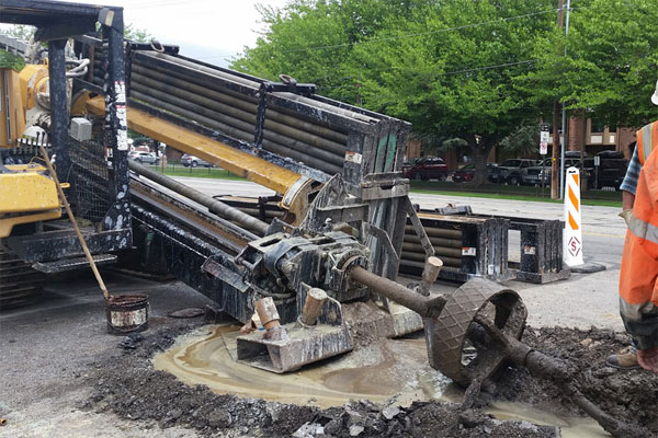
Horizontal Directional Drilling involves creating a curved underground path between an entry point and an exit point. A drilling rig positioned at the entry location pushes and rotates a drill string fitted with a steerable drill head. An operator monitors the drill head’s position and direction using a locating or guidance system and makes adjustments to maintain the planned route.
Once the pilot bore reaches the exit point, the drilling head is replaced with a reamer. The bore is enlarged through one or more reaming passes, depending on the required diameter, ground conditions and installation length. The product pipe is then connected to a pullback assembly and drawn through the enlarged bore towards the drilling rig.
Drilling fluid, usually a bentonite-based slurry or another engineered fluid, helps transport excavated soil to the surface, cool the drill head, lubricate the bore and support its walls. Its composition must be selected according to the soil or rock conditions and the project requirements.
The main stages are:
- Site investigation and route planning.
- Entry and exit area preparation.
- Pilot bore drilling and steering.
- Bore enlargement through reaming.
- Product pipe preparation and connection.
- Pipe pullback through the bore.
- Final inspection, testing and reinstatement.
Site Investigation and HDD Route Planning
Site investigation is the first major activity in HDD construction. The drilling route must be designed after evaluating the ground profile, existing underground utilities, groundwater conditions, surface restrictions and the location of the entry and exit points. Inadequate investigation can lead to drilling deviations, bore collapse, excessive pulling resistance or unplanned drilling fluid returns at the surface.
The planning stage should include the following activities:
- Geotechnical investigation: Conduct borehole drilling, soil sampling and other suitable ground investigations to identify soil layers, rock formations, groundwater levels and obstructions.
- Underground utility mapping: Identify existing water pipelines, sewer lines, gas mains, electrical cables and telecommunications ducts using utility records, detection equipment and trial pits where necessary.
- Alignment design: Establish the horizontal and vertical profile, entry and exit angles, minimum cover and permissible curvature according to site conditions and pipe requirements.
- Equipment selection: Select the drilling rig, drill rods, drill head, reamers and fluid circulation system based on bore length, pipe diameter, ground conditions and calculated installation loads.
- Work area planning: Allocate space for the drilling rig, pipe string assembly, drilling fluid tanks, excavated material, lifting equipment and spoil collection.
- Environmental assessment: Identify nearby water bodies, drainage channels, sensitive habitats and locations where drilling fluid could escape to the surface.
The designed route must account for the allowable bending radius of the product pipe and the drilling equipment’s steering capability. The profile should also maintain adequate separation from existing utilities and foundations. For projects involving highways, railways or waterways, the contractor must follow the relevant owner requirements, permits and approved crossing designs.
Equipments Used for Horizontal Directional Drilling
HDD operations require a combination of drilling, steering, fluid handling, pipe preparation and monitoring equipment. The capacity of each component must match the project’s design and ground conditions.
- HDD drilling rig: Generates the thrust, rotation and pulling force required for pilot drilling, reaming and pipe installation.
- Drill rods: Transfer rotational torque and thrust from the rig to the drill head while carrying drilling fluid through internal passages.
- Steerable drill head: Cuts through the ground and allows the operator to adjust the bore direction.
- Guidance and tracking system: Uses a downhole transmitter, locating equipment or other suitable survey technology to monitor the drill head’s position, depth and orientation.
- Reamers: Enlarge the pilot bore to the diameter required for pipe installation. The tool type depends on whether the ground consists of soft soil, mixed formations, gravel or rock.
- Drilling fluid mixing and pumping system: Prepares and circulates drilling fluid at the required flow rate and pressure.
- Mud recycling plant: Separates excavated solids from returning fluid so that suitable fluid can be reused.
- Pullback assembly: Includes the pulling head or connection, swivel and associated fittings used to connect the product pipe to the drill string or reaming assembly.
- Pipe handling equipment: Supports pipe string assembly, lifting, alignment and controlled feeding during installation.
- Monitoring instruments: Measure drilling fluid pressure, flow rate, pulling force and other parameters specified in the project plan.
Rig selection should not be based only on nominal pulling capacity. The contractor must also consider available torque, thrust, bore length, pipe diameter, ground resistance and the loads imposed on the pipe. The drill string, tooling and support equipment must be compatible with the expected operating conditions.

Pilot Bore Drilling
Pilot drilling establishes the initial underground path for the pipeline. It is one of the most important stages because deviations from the approved alignment can affect cover depth, pipe curvature, clearance from other utilities and the feasibility of completing the pullback.
The drilling rig is positioned at the approved entry point and aligned with the designed bore profile. The drill head is introduced into the ground at the specified entry angle. Drill rods are added sequentially as the bore advances towards the exit point.
During drilling, the operator uses the guidance system to track the position of the drill head and compare it with the planned route. Directional corrections are made in accordance with the equipment’s steering mechanism and the required bore profile. Readings are recorded at the frequency specified in the approved method statement.
Drilling fluid is pumped through the drill rods and discharged near the drill head. It helps cool the cutting assembly, transport excavated material towards the surface and maintain suitable bore conditions. The fluid also reduces friction and can support bore stability, depending on its properties and the surrounding ground.
Important controls during pilot drilling include:
- Confirming the rig position and entry angle before drilling begins.
- Checking the tracking system and recording the initial reference coordinates.
- Monitoring the drill head’s position, depth and inclination throughout the operation.
- Maintaining the designed separation from existing underground utilities.
- Observing drilling torque, thrust, fluid pressure and flow rate for unexpected changes.
- Monitoring the surface for drilling fluid seepage, ground heave or settlement.
- Recording the completed pilot bore profile for subsequent reaming.
If the bore deviates beyond the permitted tolerance, the operator and project engineer must assess the deviation and determine the corrective action. Continuing without addressing a significant deviation may compromise the final pipe alignment or create excessive bending stress during installation.
Bore Enlargement Through Reaming
After the pilot bore reaches the exit point, the drill head is removed or replaced with a suitable reaming tool. The reamer is pulled through the existing bore towards the drilling rig, cutting and displacing additional material to create a larger passage.
The final bore diameter depends on the outside diameter of the product pipe, pipe material, ground conditions, bore stability, drilling fluid characteristics and the installation design. A single reaming pass may be sufficient for some small installations, while larger pipelines generally require several passes using progressively larger reamers. The required clearance must be established through engineering design rather than applying one fixed ratio to every project.
The main steps in reaming are:
- Reamer selection: Choose the appropriate cutting tool for the soil or rock formation and required bore diameter.
- Initial enlargement: Pull the reamer through the pilot bore while circulating drilling fluid to remove cuttings and maintain suitable bore conditions.
- Intermediate passes: Use larger reamers in sequence where required, avoiding excessive enlargement in a single pass.
- Bore cleaning: Remove accumulated cuttings and check whether the bore is suitable for pipe pullback.
- Final bore verification: Confirm that the prepared bore can accommodate the product pipe and that the fluid circulation and bore conditions are satisfactory.
During reaming, the operator must monitor torque, pulling force, fluid pressure and returns. An increase in resistance may indicate tool wear, inadequate cuttings removal, unstable ground or an obstruction. The cause should be assessed before proceeding.
Excessive drilling fluid pressure can force slurry into surrounding soil or towards the ground surface. This event, commonly called a frac-out, is a particular concern near waterways, sensitive ground and shallow crossings. Appropriate monitoring, fluid management and response procedures should be established before work begins.
Drilling Fluid Preparation and Management
Drilling fluid plays a major role in HDD operations. It transports excavated soil, lubricates the drill string and reamer, cools the cutting equipment and helps maintain the bore during drilling and pipe installation.
Water mixed with bentonite is commonly used, while polymer additives may be selected for particular ground conditions. The fluid formulation should be designed according to the soil characteristics, groundwater conditions, equipment requirements and environmental restrictions.
Drilling fluid management involves:
- Mixing: Prepare the fluid using controlled quantities of water, bentonite and any approved additives.
- Property testing: Monitor relevant properties, such as viscosity, density, sand content and other parameters specified in the project method statement.
- Circulation: Maintain sufficient flow to transport cuttings without exceeding the allowable pressure for the formation.
- Solids separation: Use screens, desanders, desilters or other suitable equipment to separate excavated solids from returning fluid.
- Reuse and adjustment: Recondition recovered fluid where suitable, adjusting its properties before recirculation.
- Waste handling: Collect spent slurry and drill cuttings and transport or dispose of them through approved procedures.
Drilling fluid should not be treated as a standard mixture that works for every soil type. Its properties need to be adjusted as ground conditions change. Poor fluid management can contribute to bore instability, excessive drag, blocked circulation and uncontrolled fluid returns.
Product Pipe Preparation and Pullback
Pipe pullback is the final installation stage, in which the prepared pipeline is drawn through the enlarged bore. The pipe must be inspected, assembled and positioned before the operation begins because interruptions or damage during pullback can result in costly repairs.
The product pipe may be made from high-density polyethylene (HDPE), steel or another material approved for the project. Material selection depends on the service, operating pressure, pipe diameter, ground conditions, jointing method and expected installation loads.
Pipe preparation
Before pullback, the contractor should complete the following activities:
- Pipe inspection: Check pipe dimensions, surface condition, joint quality and identification markings.
- Pipe string assembly: Join pipe sections using the specified method. For HDPE pipes, this commonly involves butt fusion performed under controlled conditions.
- Joint inspection: Verify alignment, fusion records and joint integrity in accordance with the approved procedure.
- Pulling head installation: Fit an appropriate pulling head or connection that transfers the installation load safely to the pipe.
- Pipe string alignment: Position the assembled pipe along a prepared working area, keeping it free from sharp bends, contamination and obstructions.
- Load verification: Confirm that the pipe, joints, pulling head and associated components can withstand the predicted installation loads.
Pullback procedure
The prepared pipe string is connected to the drilling assembly using a suitable pulling arrangement and swivel. The swivel prevents drill-string rotation from being transferred directly to the product pipe. The rig then pulls the assembly back through the enlarged bore while drilling fluid continues to circulate as required.
During this operation, the crew must maintain communication between the rig operator, pipe-handling team and monitoring personnel. Pulling force, fluid pressure, fluid returns and pipe movement should be observed throughout the installation.
Key precautions include:
- Maintain the pulling force within the allowable limit specified for the pipe and installation system.
- Avoid sudden changes in pulling speed and unnecessary interruptions.
- Ensure that the pipe follows the planned entry and exit geometry without exceeding its permitted bending radius.
- Monitor the pipe surface for abrasion, deformation or other damage.
- Keep the pulling path clear of personnel and equipment.
- Follow the approved response procedure if pulling resistance increases unexpectedly or drilling fluid circulation is lost.
Where an interruption occurs, the team should assess bore conditions, pipe position and pulling resistance before restarting. Pullback should not be forced beyond the allowable loads merely to complete the installation.
Post-Installation Inspection and Quality Control
Once the pipe has been installed, the contractor must verify that the pipeline meets the design and service requirements. Inspection and testing depend on the pipe material, intended use, operating pressure and applicable project specifications.
The quality control process generally includes the following checks:
- Alignment verification: Compare the installed route with the planned profile and available tracking records.
- Pipe condition inspection: Check accessible sections for scratches, deformation, coating damage or other defects.
- Joint verification: Review fusion records, weld inspection results or other joint quality documentation.
- Pressure testing: Conduct the specified hydrostatic or other approved pressure test for pressure pipelines.
- Leak testing: Perform the applicable leakage or integrity test for the intended service.
- Cleaning and flushing: Remove debris and other contaminants from pipelines where required.
- Internal inspection: Use suitable inspection equipment where specified by the project.
- As-built documentation: Record the installed alignment, depth data where available, pipe details, joints, test results and any approved changes.
For water supply pipelines, cleaning, disinfection and water quality checks may also be necessary before commissioning. Sewer pipelines require checks appropriate to their design and service, while gas pipelines must meet the relevant requirements for material, joint integrity, pressure testing and commissioning.
The project quality plan should define inspection hold points, acceptance criteria, documentation requirements and the responsibilities of the contractor, consultant and asset owner. These checks help confirm that the pipeline is ready for commissioning and future maintenance.
Common Challenges in HDD Pipe Installation
HDD reduces the need for continuous surface excavation, but it introduces specific construction risks that must be addressed through design and monitoring.
- Bore deviation: The drill head may move away from the planned alignment because of changing ground conditions, obstructions or steering limitations. Regular tracking and timely correction help maintain the designed profile.
- Bore collapse: Loose or unstable soil can cause the bore to deteriorate before pipe installation. Appropriate drilling fluid properties, bore design and control of the time between reaming and pullback help manage this risk.
- Excessive pulling force: High resistance may result from inadequate bore enlargement, accumulated cuttings, tight curvature, friction or unsuitable fluid conditions. The installation plan must establish allowable loads and corrective procedures.
- Drilling fluid escape: Fluid may migrate through permeable ground, fractures or weak zones and emerge at the surface. Pressure and return-flow monitoring, along with a planned response procedure, help control the consequences.
- Damage to existing utilities: Inaccurate utility records or insufficient separation can lead to conflicts with existing services. Utility mapping, verification and continuous bore tracking are therefore necessary.
- Pipe damage during installation: Excessive bending, abrasion, poorly prepared joints or uncontrolled pulling can affect pipe integrity. Proper pipe handling and load monitoring help reduce these risks.
- Difficult ground conditions: Gravel, cobbles, hard rock, mixed formations and groundwater can affect drilling speed and tool performance. Ground investigation and appropriate selection of the drill head, reamer and drilling fluid are important for maintaining control.
Conclusion
Horizontal Directional Drilling provides an effective method for installing underground pipelines where conventional excavation would cause significant surface disruption or encounter physical restrictions. Its success depends on coordinated planning, accurate pilot drilling, controlled bore enlargement, suitable drilling fluid management and careful pipe pullback.
For civil engineers, contractors and infrastructure developers, the most important consideration is to treat HDD as an integrated engineering process rather than simply a drilling operation. Geotechnical investigation, utility mapping, equipment selection, load calculations, quality control and environmental monitoring must be addressed from the design stage through commissioning. When these activities are managed in accordance with approved specifications, HDD can support the installation of reliable underground utility networks while reducing disruption to existing infrastructure.