Selecting the right pin count for a circular connector is rarely as simple as counting the conductors in your schematic and grabbing the next available insert. In complex industrial or aerospace systems, the contact arrangement changes drastically with the position count. These layout changes directly impact the current capacity, contact size, wiring density, installation space, and ultimately, the safety of the circuit.
This decision becomes particularly critical when a single interface must combine both power and control signals. Choose too few positions, and you leave no room for future expansion. Choose too many, and you may be forced to use smaller contacts that overheat under load, while unnecessarily complicating the assembly process. A robust selection always begins with analyzing the electrical load, followed by considerations for termination, mechanical integration, and testing.
Classify Circuits Before Counting Pins
A common mistake hardware engineers make is treating one motor conductor, one sensor return, and one communication line as three mathematically equivalent “pins.” Instead, start with a comprehensive circuit schedule.
For every conductor, record its specific function, nominal current, maximum peak current, working voltage, conductor size, shielding requirements, and safety relevance. Power circuits should always dictate your contact-size decisions. High-draw applications like heaters, charging interfaces, or actuators demand larger contacts. On the other hand, sensor and communication circuits usually draw minimal current but are highly sensitive to contact resistance and electromagnetic coupling (EMI).
If your project combines power and signals in one connector envelope, you must verify that the specific insert is designed for mixed-signal applications. In many heavy-duty applications, physically separating high-current power from sensitive feedback data into two different interfaces is the safest architectural decision.
Match Contact Capacity to the Actual Load
Once your circuits are classified, compare the worst-case electrical demand against the rating of the connector’s configuration. Always use the maximum continuous current rather than the typical operating value, and ensure you account for simultaneous loading across multiple contacts in the same housing.
Remember that ambient temperature, enclosure heat, cable bundling, and termination quality can severely degrade the theoretical current capacity. The same applies to voltage limits. Do not use a spare contact to carry additional current unless the connector’s datasheet explicitly supports parallel contacts—unequal resistance can cause thermal runaway.
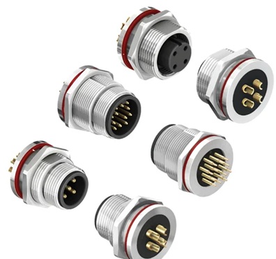
When your current requirements are strict, relying on high-quality, standardized components is essential. For instance, utilizing a rigorously tested dp series aviation connector ensures that both the dielectric requirements and the creepage clearances are met for harsh environment applications.
The Myth of “Extra Pins Are Always Better”
Leaving one or two positions empty for future equipment upgrades can be highly practical. A reserved contact might save you from having to punch a new panel cutout or completely redesign the wire harness later down the line.
However, the assumption that “extra pins are always better” is a dangerous habit. Moving up to a higher pin-count tier often shrinks the size of every contact in the insert, which lowers the overall current rating and changes the cable termination space. Furthermore, unused positions must be meticulously documented; otherwise, field technicians may mistakenly treat them as unidentified faults or attempt to use them as convenient spare power paths.
A safer engineering method is to list every expected future function, estimate its electrical load, and assign a tightly controlled, reserved position in your pin map.
Termination and Mechanical Integration
Finally, the termination method must match your assembly and service environment. Solder termination provides a highly compact and permanent joint, ideal for factory-built harnesses that will rarely be serviced. Screw or crimp terminations, however, simplify field wiring and conductor replacement, provided the technicians use the correct torque and stripping lengths.
Before finalizing the pin count, confirm the rest of the mechanical system. Will the selected cable’s outer diameter actually fit through the backshell? Do the cable gland and strain-relief system match the finished bundle? A connector can have the perfect pin count and still fail the installation review if the cable cannot bend, seal, or terminate properly within the confined space.