
Pneumatic piercing can place a small service, duct, or conduit beneath a driveway, sidewalk, or other finished surface without opening a continuous trench. Its compact setup makes a short crossing look simple. The harder question is whether an unsteered displacement bore has enough tolerance for the route and whether the complete air system can keep the selected tool working correctly.
Available GRUNDOMAT piercing tools cover a wide range of diameters and air demands. Choose a model only after defining the product size, soil conditions, bore length, permitted departure, utility clearances, and compressor capacity. A larger tool is not automatically safer or more productive. It displaces more soil, needs more cover and launch space, and may require several times the airflow of a smaller model.
Accuracy, soil, launch setup, tool condition, and compressed-air delivery form one system. A weakness in any part can turn a suitable short bore into a miss, a stalled tool, surface heave, or an unplanned recovery excavation.
Where Pneumatic Piercing Fits
A conventional piercing tool is a cylindrical pneumatic hammer with a displacement head. An internal piston delivers repeated impacts that move the body forward. The nose pushes soil outward around the tool rather than cutting and removing spoil. Depending on the installation arrangement, the product pipe may be pulled behind the tool or installed after the bore is complete.
This method suits straight, small-diameter installations in ground that can be displaced and will provide reasonably balanced support around the tool. Typical uses include water and gas services, irrigation lines, telecommunications duct, electrical conduit, and other short crossings under finished surfaces.
The absence of spoil simplifies the site, but it creates two limits. The surrounding ground must accept the displaced volume without unacceptable heave or settlement. Most conventional piercing tools also cannot be steered after they enter the bore. The launch establishes the trajectory; the soil then influences how closely the tool follows it.
Pneumatic piercing is a weak fit when the route requires active corrections, exact grade throughout the crossing, or a narrow clearance beside an existing utility. Solid rock is outside the intended application. Loose granular soil may not hold an unsupported opening, while very soft or saturated material can let the tool swim or lose forward grip. Mixed fill, cobbles, roots, demolition debris, and old utility trenches create changing resistance that can push an unsteered tool away from its planned path.
Select the method from the full route, not bore length alone. A 25 ft shot through uncertain construction fill can present more directional risk than a longer shot through uniform cohesive soil.
What Accuracy Evidence Supports
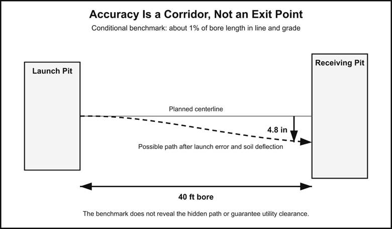
Published guidance does not support one universal accuracy number. The often-cited benchmark is that an unsteered mole may remain within about 1 percent of bore length in both horizontal line and vertical grade when the ground is stable and the launch is aligned correctly. This is a conditional planning reference, not a guaranteed result or an average measured across jobs.
The practical size of that allowance grows quickly:
| Bore length | 1% departure in line | 1% departure in grade |
| 20 ft | 2.4 in | 2.4 in |
| 30 ft | 3.6 in | 3.6 in |
| 40 ft | 4.8 in | 4.8 in |
| 50 ft | 6.0 in | 6.0 in |
These figures apply separately in two planes. They do not define a circular envelope, describe the path between the pits, or state the probability that a tool will remain inside the allowance. The evidence review of pneumatic piercing accuracy for FTTH drop bores explains why exit-point error, line and grade, path deviation, and repeatability are different measurements.
A receiving pit can hide error. If the pit is 3 ft wide, a tool may enter it after departing substantially from the intended centerline. That outcome confirms recovery at the endpoint, but it does not prove the hidden bore maintained clearance from a sewer lateral, gas line, or electrical duct midway along the route.
For a 40 ft crossing, the conditional 1 percent benchmark equals 4.8 in horizontally and 4.8 in vertically. If the permitted corridor is only 3 in wide, the benchmark already exceeds the design tolerance before rocks, fill changes, tool wear, or launch error are considered. A guided method, a different route, or exposure of the conflict is then a stronger choice.
Launch Error Consumes the Tolerance Early
Initial angular error grows with distance. A half-degree aiming error produces about 2.1 in of straight-line offset at 20 ft and about 5.2 in at 50 ft. Those values describe geometry only; real soil can add, reduce, or redirect the departure.
Visual aiming from one pit to another is therefore insufficient for a tight crossing. The launch cradle must remain stable, and the target must establish both horizontal line and vertical grade. Once the tool is fully in the ground, monitoring can show where it is going, but a conventional tool cannot be steered back to the planned line.
How Soil and Launch Setup Change the Result
Uniform soil gives the tool relatively balanced resistance. Variable ground encourages it to follow the path of least resistance. The same model can hold line on one property and deflect on the next, even when the bore length and launch procedure appear identical.
The following ground descriptions are screening categories, not guarantees:
Uniform clay or silt usually provides consistent support when moisture and density remain moderate.
Very soft or saturated soil can allow swimming, oscillation, or loss of forward grip.
Loose sand or gravel can collapse behind the tool unless the product is pulled during boring.
Dense or dry material increases resistance and may cause slow advance, refusal, or deflection.
Mixed fill, roots, cobbles, and old trench backfill create abrupt changes that can redirect the tool.
The launch and receiving pits reveal only two points along the route. Material between them may include a former service trench, pavement base, landscaping fill, or buried debris. Compare records and surface evidence with the material visible in both pits. Treat unexplained transitions as uncertainty rather than assuming uniform ground.
Control the Part of the Trajectory That Is Controllable
Manufacturer guidance for the GRUNDOMAT P and PK family calls for a reduced-power launch with repeated checks of line and grade while the tool enters the ground. Full airflow is applied only after alignment is confirmed and the tool is sufficiently committed to the bore. A larger model or critical alignment may require a secured starting cradle rather than support on the pit floor alone.
The same manual warns that excessive advance speed can increase the chance of going off course and instructs the operator to reduce air if boring speed exceeds 60 ft per hour. Slow progress is not automatically an air-supply problem. Dense soil, unstable material, an obstruction, worn seals, poor lubrication, or a restricted air line can produce similar symptoms.
Cover depth matters because the tool creates its opening by displacement. TT gives a minimum working-depth guideline of ten times the tool diameter for the models covered by its manual. A 3 in tool therefore implies at least 30 in of cover under that model-specific rule. The project design, product diameter, pavement structure, utility owner, and local requirements may demand more.
How to Match Compressor Capacity
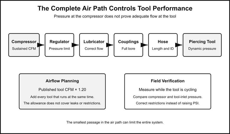
Pressure and airflow perform different jobs. Pressure supplies force; airflow sustains the piston cycle. A compressor gauge can show the expected PSI while the tool is still starved for CFM through a long hose, restrictive coupler, undersized regulator, inadequate lubricator, or leak.
Current North American GRUNDOMAT maintenance guidance states that the tool should not be operated above 95 psi at its inlet and that compressor pressure should remain at or below 105 psi while the tool is running. The exact manual for the model and generation on the job must control because older documentation may list different limits.
Use this airflow screen:
Identify the exact tool model and documentation family.
Find its published air consumption in CFM.
Add the demand of every tool that may run at the same time.
Apply the manufacturer’s approximately 20 percent allowance for increased demand as seals wear, where that guidance applies.
Compare the result with the compressor’s sustained output at the required working pressure.
Verify dynamic pressure at the tool inlet during an above-ground operating test.
A 75 P is listed at 32 CFM. Applying a 20 percent planning allowance gives 38.4 CFM. Two 75 P tools would require 76.8 CFM before external leaks, other air users, or restrictions are considered. A detailed compressor-capacity calculation for pneumatic piercing tools shows how published model demand, simultaneous use, hose length, and dynamic pressure fit together.
Increasing pressure does not cure an airflow shortage. If a compressor delivers 50 CFM and the tool continuously consumes 64 CFM, a receiver tank can only delay the pressure drop. It cannot supply the missing 14 CFM for the duration of the bore.
Check the Complete Air Path
Air must travel through the regulator, lubricator, valves, couplings, supply hose, extensions, whip hose, and tool inlet. The smallest internal opening can limit the entire system even when the main hose looks large enough. Long runs, kinks, contamination, worn fittings, leaks, and moisture add further loss.
Measure pressure while the tool is cycling, as close to the inlet as the approved test arrangement permits. A static reading before the tool starts is not a capacity test. Compare compressor pressure and tool-inlet pressure at the same moment. If the drop is excessive, isolate the restrictive section instead of turning the regulator above the permitted limit.
Cold conditions add another failure mode. Compressed air cools as it expands, and moisture can freeze inside the tool. Correct lubrication, water separation, drainage, and approved cold-weather equipment matter as much as nominal compressor output. Insufficient lubrication can also accelerate seal wear and raise apparent air demand.
How to Select the Tool and Accessories
Tool diameter is only the first filter. The selected package must fit the installed product, soil response, available cover, compressor, hose, launch pit, recovery plan, and accuracy corridor. Models with similar diameters may differ in body length, weight, stroke rate, and airflow.
Representative current North American specifications show the range:
| Model | Tool diameter | Weight | Published airflow | Airflow with 20% planning allowance |
| 45 P | 1.75 in | 20 lb | 12 CFM | 14.4 CFM |
| 65 P | 2.5 in | 55 lb | 25 CFM | 30.0 CFM |
| 75 P | 3.0 in | 75 lb | 32 CFM | 38.4 CFM |
| 95 P | 3.75 in | 143 lb | 53 CFM | 63.6 CFM |
| 110 P | 4.25 in | 212 lb | 64 CFM | 76.8 CFM |
| 130 P | 5.0 in | 258 lb | 92 CFM | 110.4 CFM |
The allowance column is a planning calculation based on TT’s maintenance guidance, not a replacement specification. It accounts for increased tool demand associated with seal wear. It does not cover leaks, another air consumer, altitude effects, or undersized components.
Start From the Product and the Bore
Define the outside diameter and stiffness of the product, whether it will be pulled during boring or installed afterward, and whether an expander or sleeve is required. Oversizing the bore without a ground-response reason increases displacement and may increase surface risk. Undersizing can damage the product or prevent installation.
Next, compare the model’s weight and length with the pit geometry and handling plan. A 258 lb tool changes the launch, lifting, and recovery requirements substantially compared with a 55 lb tool. The receiving pit also needs enough space to recover the body safely without enlarging the excavation after the shot.
Then match the complete accessory group. The regulator, lubricator, coupling bore, hose diameter, whip hose, safety devices, pulling hardware, and alignment equipment must support the chosen model. Matching thread size alone does not establish adequate flow capacity.
Finally, identify the exact manual and parts configuration. P, PK, Servo, and P+ designations should not be treated as interchangeable. Two tools with similar nominal diameters can have different airflow and operating requirements. For used equipment, confirm the serial identity, inspect the head and casing, check hose and coupling condition, and perform the manufacturer-approved surface function test. A successful surface cycle confirms basic operation, not underground directional accuracy.
A Practical Prelaunch Decision
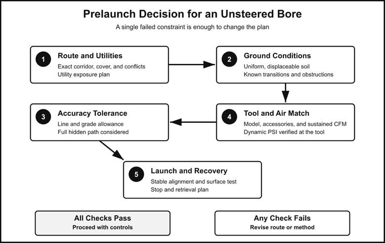
The bore is a reasonable candidate for pneumatic piercing when the route is short and straight, the ground appears consistently displaceable, the permitted corridor accommodates realistic departure, and critical crossings can be located or exposed. The selected tool must fit the product and available cover, while the compressor and full air line must support sustained operation within the applicable pressure limit.
Before launch, confirm all of the following:
The planned line, grade, cover, and receiving area are defined in inches rather than by approximate visual alignment.
Existing underground installations have been located under the applicable one-call, owner, project, and regulatory procedures.
Critical or uncertain crossings have been exposed or otherwise verified by an approved safe method.
The route does not depend on an unsteered tool making a correction after launch.
Soil observations and records do not show an unexplained transition, obstruction, or unstable zone that defeats the tolerance.
The exact tool model, head, product connection, hose, regulator, lubricator, and couplings are compatible.
Compressor capacity exceeds the planned sustained airflow at the required pressure.
Dynamic pressure has been checked at the tool during a surface run.
Lubrication, moisture control, forward operation, and reverse operation have been checked under the applicable manual.
The crew has a defined stop, reverse, recovery, or relaunch plan.
Choose another method or revise the route when exact depth must be maintained throughout the bore, the permitted departure is materially smaller than the conditional accuracy benchmark, mixed ground is likely, a critical utility occupies a narrow corridor, or the consequence of a miss is high.
Utility location deserves particular weight. Federal excavation requirements call for estimating underground installation locations before excavation and determining exact locations by safe and acceptable means as work approaches them. One-call markings alone may not identify every private or nonmetallic sewer lateral. A PHMSA and NAPSR survey found that 70 percent of respondents recognized pneumatic piercing as a cross-bore threat, and 14 of 23 responding states reported sewer cross-bore incidents or near misses. That survey does not measure tool accuracy, but it shows why reaching the exit pit is not an adequate safety test.
Base the final decision on the narrowest constraint. If the route can tolerate an unsteered bore but the compressor cannot sustain the tool, choose a smaller compatible model or a larger air system. If the air package is adequate but the utility corridor cannot tolerate several inches of uncertainty, change the method or verify the conflict. The right piercing tool fits the product, ground, tolerance, air supply, and recovery plan at the same time.