

ABSTRACT: This paper explores the extensive structural retrofitting applied to the Birendra Sasmal Setu Bridge, a 50-year-old Prestressed Concrete (PSC) bridge on National Highway-14, in the district of Paschim Medinipur, West Bengal, India. The bridge, which had experienced significant deterioration due to poor-quality of materials and workmanship and severe honeycombing in the T-beam girders, was initially deemed unfit for service and recommended for reconstruction of new bridge. However, through innovative retrofitting techniques, the bridge’s deficiencies were addressed, allowing it to pass the load tests required by IRC standards and be reopened with some amount of traffic restrictions.
1. INTRODUCTION
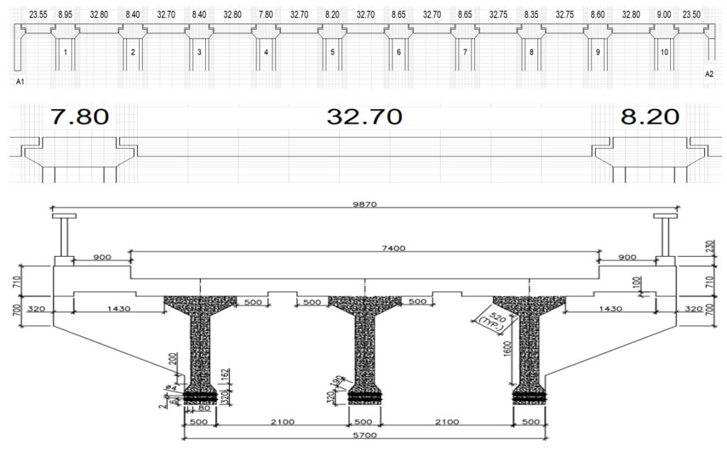
The bridge is named after Birendra Sasmal (who was a lawyer and a political leader of Medinipur and was very active in Swadeshi movement) and is a two-lane 425.44 meter long simply-supported PSC girder road bridge on NH60 (New NH-14) at chainage 118.700 km, which was constructed across the river Kangsabati and opened for traffic in 1972, in the district of Paschim Medinipur (the then unified district of Medinipur), West Bengal. The bridge connects two major towns Kharagpur and Medinipur which are around 15 km away from each other, apart from being an important connecting link of NH-60 (New NH-14), from the junction of NH-6 (New NH-16, G-Q NH between Kolkata and Mumbai) connecting NH-2 (New NH-19, another G-Q NH between Kolkata and Delhi and ends at NH-34 (New NH-12) at Moregram. It has 9 numbers of 32.70m long PSC T-beam simply supported spans and 2 numbers of 23.50m long PSC T-beam spans between two abutments. Each span is supported by 3 PSC girders and several cross beams. The spans were rested on 10 numbers of butterflies (hollow hammerheads) with around 8.50mt road length over it. The butter flies acted as pier-caps for the concrete piers that were constructed on well foundations across the river. General arrangement drawing of the bridge is shown in figure 1.
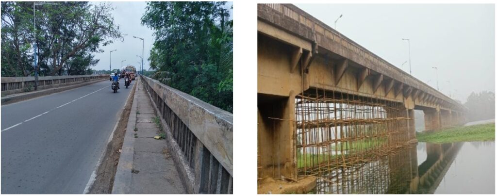
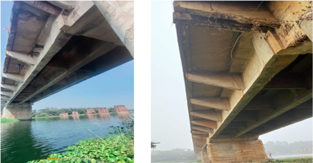
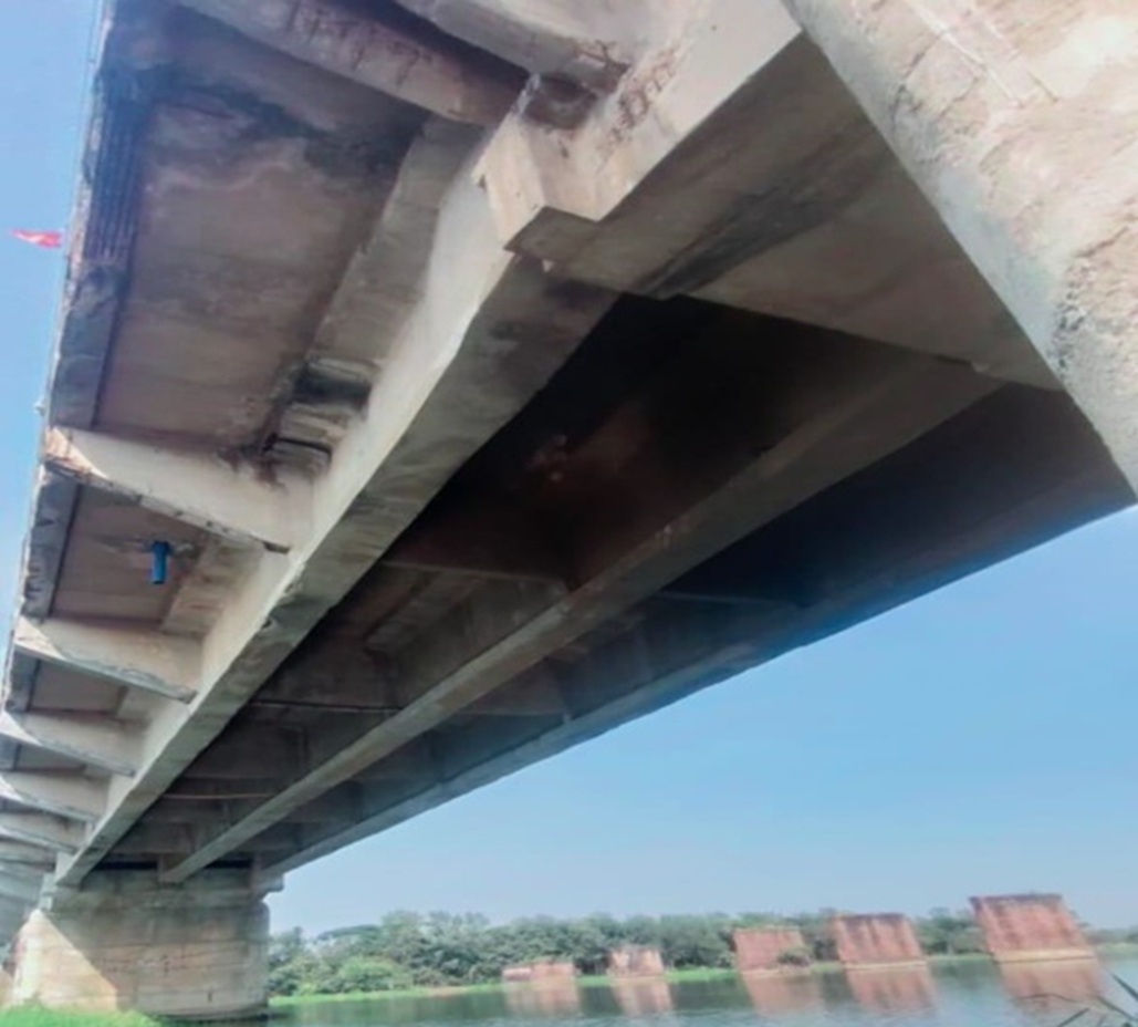
The Public Works Department (PWD), NH Wings of the Govt of West Bengal appointed a technical consultant to evaluate the structural condition of the bridge in the year 2022. Upon inspection, several critical distresses were found such as large honeycombs around congested existence of reinforcement, snapped PT tendons, low strength of concrete and reduction of sectional area of members at many locations. This had resulted in loss of serviceability and appearance of structural cracks due to loss of flexural and shear strength. Considering the existing condition at the time, the consultant recommended to immediately stop all heavy vehicles through the bridge and construct the new bridge on urgent basis. They have suggested an alternative Bailey Bridge to make the traffic flow operational.
The bridge held high strategic importance to the major towns that it connects. As there would be substantial direct impact on the livelihood of the town dwellers as well as on cargo movement, services, and public transport due to stopping traffic through an important NH bridge, the PWD, NH wing, West Bengal could not consider this as a straightforward engineering decision. Bailey bridge construction option for a length of around 450 mt with foundations is no less costly and thus not considered to be a feasible solution. Hence, it was decided to restore the structural performance of the bridge through detailed structural retrofitting solutions till the time an alternative infrastructure is constructed and put into service. The DPR of restoration of the damaged bridge was prepared and the sanction from MoRTH was obtained. After that, a procurement process was initiated (selection of agency in EPC mode) to appoint a suitable contractor for design-build solution, which was awarded to Sanrachana Structural Strengthening Pvt. Ltd, Thane West, Mumbai, Maharastra as L-1 bidder on November, 2022.
Using the initial analysis based on consultant’s technical report, it was found that because of deficiencies in some structural members, the existing condition somehow could not match what ACI (American Concrete Institute) permits to be handled though FRP (Fibre Reinforced Polymer) based solutions. The other alternative solutions involved external post tensioning, which was also not feasible due to insufficient strength of concrete. Since it was a 50-year-old bridge and the original drawings and structural design documents were not available, analysis performed on speculative structural models are only as good as the rational estimations based on site observations and different modes of NDT. Therefore, a closer look was necessary before formulation of any retrofitting methodology and planning.
2. INITIAL CONDITION
The first observation made by the EPC contractor (Sanrachana Structural Strengthening Pvt. Ltd) at site was the highly perceivable vibrations on the bridge decks upon passage of heavy vehicles. It was clear that the serviceability has been severely affected. After setting up scaffoldings, the underside of the bridge was inspected, to reveal the major distresses such as fully exposed bottom reinforcements along with PT duct (Photo:3). The rebars were MS bars, typically of 50-year-old with smooth surface. The extreme congestion of rebars as well as prestressing sheathing pipes have prevented the concrete from reaching the bottom bulb portion in many locations of the girder. This has caused corrosion of PT ducts, wires and rebars. The wires and rebars looked almost similar to each other in the corroded condition. Since there is no bond between the steel and concrete in these locations, load transfer would not happen as intended by design. Additionally, the snapped PT wires were a major source of concern.
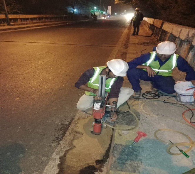
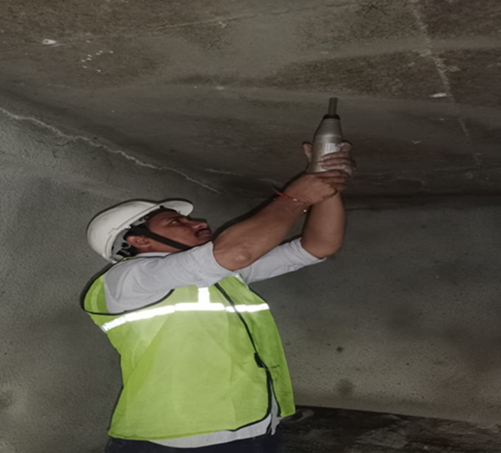
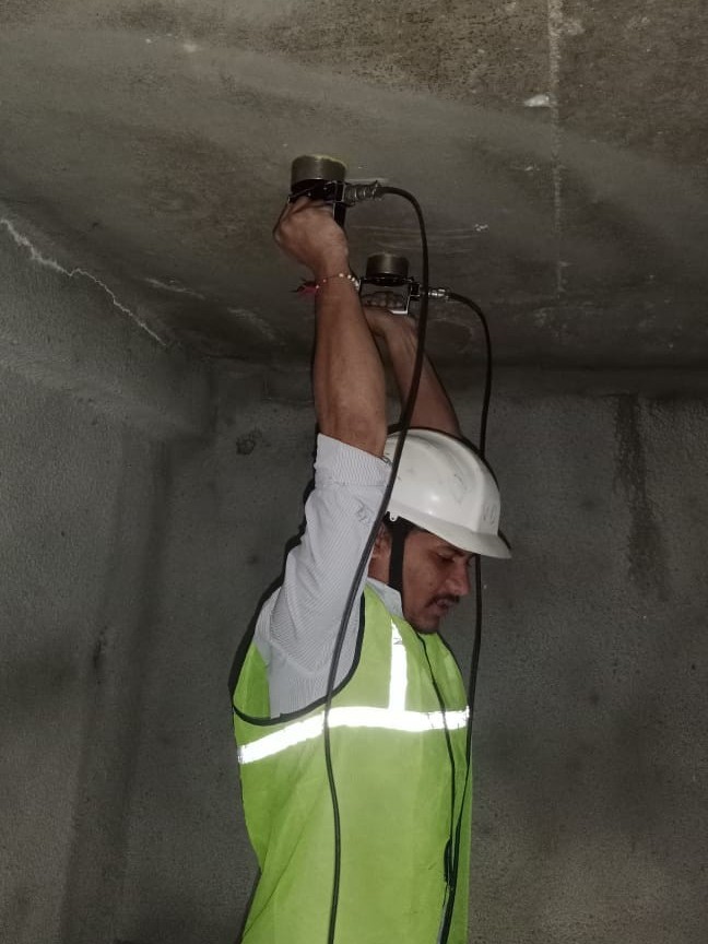
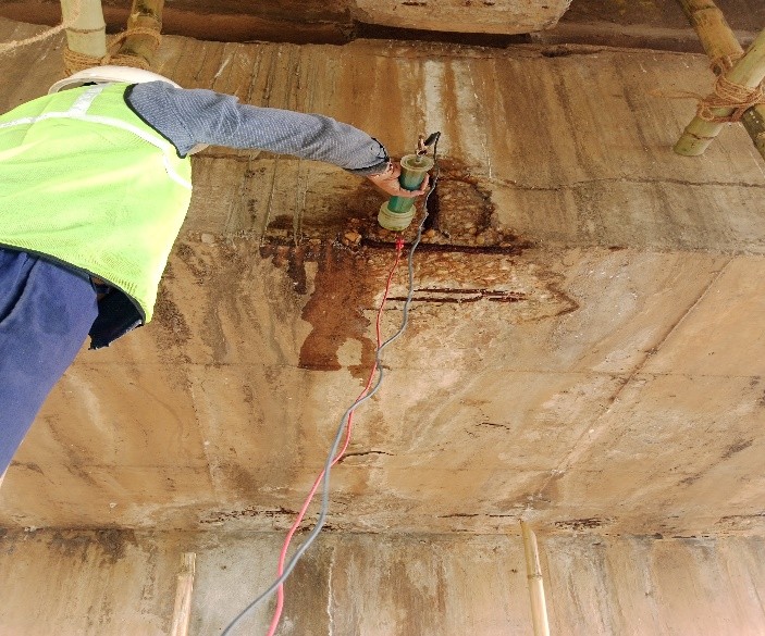
Detailed NDT was conducted (Photo:4 a,b,c and d) and an attempt was made to locate the embedded PT tendons through GPR (Ground Penetration Radar) scanning. The visibly dilapidated portions were excluded from NDT as those portions certainly need intervention. Hence various modes of NDT were conducted on relatively good portions to ascertain the quality of apparently sound looking concrete. In the deck slabs and girders, UPV (Ultrasonic Pulse velocity) results pointed at high probability of corrosion, which was evident from visual observation at several locations. Though rebound hammer values were obtained in 30-40MPa range, the core compressive strength value in girders was below 30 MPa at almost all test locations, indicating increase in surface strength through carbonation. UPV readings as low as 1.69km/s were obtained which was the indication of poor concrete.
These findings indicate that the concrete was not at par to match the minimum requirements laid out as per IS standards for prestressed concrete, as evident from the distresses observed in site.
Unless the microstructure of concrete of several structural members of the bridge is improved, modern strengthening measures using high-strength materials like Carbon FRP (CFRP) is not advisable, since the local stresses generated by strengthening measures may be too high for the concrete to bear, resulting in abrupt failure of the existing bridge structure upon heavy vehicular movement.
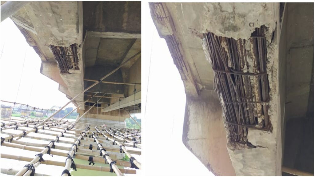
Inspection Findings:
The bridge was found to be in a deteriorated condition due to various factors:
- Honeycombing: Large honeycombed areas in the T-beam girders indicated poor concrete compaction.
- Corrosion: Exposure of bottom reinforcements and snapped post-tensioning (PT) tendons highlighted significant corrosion problems.
- Concrete Quality: The concrete strength was low, with core compressive strengths below 30 MPa and UPV values indicating high porosity and potential for corrosion.
- Structural Deficiencies: The overall serviceability was compromised, with visible structural cracks and reduced flexural and shear strength.
2.1 Detailed Condition Assessment
2.1.1 Concrete Quality and Non-Destructive Testing (NDT)
Compressive Strength Testing:
- Coring: As per (IS 516 Part 4), core samples were extracted from various locations and structural members of the bridge for laboratory testing. Core diameters typically ranged from 100 mm to 150 mm, and the samples were tested for compressive strength using a universal testing machine. The average compressive strength of some members was not found to be matched the desired strength due to poor concrete and aging.

Rebound Hammer Test:
- Procedure: As per (IS 516 Part 2 Sec 4, BS 1881 Part 202), the Schmidt hammer was used to estimate the surface hardness/strength of concrete. Readings were compared with standard correlations to estimate the compressive strength. This method was less reliable in highly deteriorated concrete but provided a quick estimate of relative concrete strength.

Ultrasonic Pulse Velocity (UPV):
- Testing: As per (IS 516 Part 5 Sec 1, BS 1881 Part 203), UPV testing measured the time taken by an ultrasonic pulse to travel through the concrete. A lower velocity indicated poor concrete quality and high porosity. The velocities obtained (1.69 km/s) confirmed deterioration of concrete to a considerable extent.

Concrete Resistivity:
- Measurement: Electrical resistivity testing was used to assess the likelihood of reinforcement corrosion. Low resistivity values indicated high corrosion potential.

2.2 Structural Crack Analysis
Crack Mapping:
- Survey: A detailed survey of cracks was conducted using visual inspection and measurement tools. The cracks were categorized based on width, length, and orientation.
Crack Width Measurement:
- Gauges: Crack width gauges were used to measure the width of cracks over time. This helped in assessing the progression of damage and effectiveness of the repair measures.
Crack Filling Techniques:
- Epoxy Injection: For fine cracks, epoxy resins were injected under pressure. This method effectively bonded the crack surfaces and restored the structural integrity to some extent.
3. CHALLENGES
The bridge happens to be located on a busy stretch of the National Highway, that conveys heavy traffic volume daily. The strategic location of the bridge makes it difficult to undergo a complete shutdown, hence repairing was required to be performed while light traffic was operational.
3.1 Traffic Management
The bridge’s location on a major national highway necessitated performing repairs with minimal traffic disruption. A detailed traffic management plan was required to manage the flow of heavy vehicles and ensure safety during repairs. District Administration accordingly arranged the detouring of the heavy vehicles during the retrofitting work.
3.2 Concrete Strength
The low strength of the original concrete posed a significant challenge. High stress concentrations from retrofitting measures needed to be managed with due care to prevent premature failure. Repair methodology must first address the low strength of the concrete, so that the structural members shall not fail locally due to high and concentrated load transfer between concrete and applied strengthening material.
3.3 Snapped PT Tendons
Working on girders that have snapped PT tendons was the most challenging part of the job. Designers at-times even ignored the moment of resistance offered by reinforcing steel in prestressed girders, since moment capacity due to reinforcement bars are small in comparison to the resistance offered by PT tendons. Hence snapping of these cables may have serious implications on the serviceability and structural safety of the bridge.
Replacement of corroded PT tendons is not possible, as the ducts are partly grouted.
3.4 Bearing Rectification
Tilted bearings need to be rectified by lifting the spans using hydraulic jacks. As the concrete quality is low, the relatively high stress concentrations generated by hydraulic jacks can lead to disastrous results, especially since there is visible confirmation of snapping of PT stands.
4. REPAIR AND REBUILDING OF DIFFERENT STRUCTURAL MEMBERS OF THE DILAPIDATED BRIDGE
Before applying the strengthening measures, a lot of preparatory work was done as follows:
4.1 Removal of Loose Concrete
Process:
- Scaffold Erection: Scaffolding was set up to provide access to the bridge’s underside.
- Concrete Removal: Loose and delaminated concrete was removed using hand tools to minimize vibration and prevent further damage.
Considerations:
- Manual Chipping: Mechanized chipping was avoided to prevent excessive vibrations and further structural damage.
- Hand Chipping: Used for controlled removal of deteriorated concrete to prevent further damage. Tools included chisels and pneumatic hammers.
- Water Jetting: High-pressure water jets were used in certain areas to remove loose concrete without damaging the underlying structure.
Preparation for Repair:
- Surface Cleaning: After concrete removal, surfaces were cleaned with compressed air to remove dust and debris, ensuring a good bond with repair materials.
4.2 Pressure Grouting (Photo:5)
Procedure:
- Crack Preparation: Cracks were widened using a grinding wheel to ensure effective grout penetration.
- Grouting: Thixotropic putty was used to seal cracks, followed by pressure grouting with low-viscosity cement grout to fill voids and improve concrete microstructure.
Materials:
- Cement Grout: Used for its ability to penetrate fine cracks and voids. Typically composed of Ordinary Portland Cement (OPC) mixed with water and fine aggregates. Admixtures were used to improve flow and bonding.
- Epoxy Grout: Applied in areas requiring higher strength and durability. Used for higher strength requirements. It consists of epoxy resins and hardeners that provide excellent adhesion and resistance to environmental factors.
Grouting Process:
- Port Installation: Grouting ports were installed at strategic locations. These ports allowed the injection of grout into the cracks and voids.
- Pressure Application: Grout was injected under controlled pressure to ensure complete filling of voids.
4.3 Reinforcement Steel Binding and Anti-Corrosive Treatment (Photo 6).
Process:
Surface Preparation:
- Rust Removal: Mechanical wire brushing and sandblasting were used to clean the steel reinforcement. This process removed rust and scale to prepare the steel for coating.
- Cleaning: Exposed steel reinforcement was scrubbed with wire brushes to remove corrosion products.
- Anti-Corrosive Coating: A rust-converting primer was applied to neutralize rust, followed by an epoxy coating to protect against future corrosion.
Materials:
- Alkaline Rust Converting Primer: A rust-converting primer was applied to react with existing rust and create a stable base for further coating.
- Epoxy Coating: Applied as a protective layer to prevent moisture and chemicals from reaching the steel.
- Bonding Techniques:
- Epoxy Adhesive: High-strength epoxy adhesives were used to bond additional reinforcements or CFRP sheets.
4.4 Rebuilding Sections (Photo 7)
Materials Used:
- Micro-concrete: Applied in areas where significant concrete loss occurred. It has a high compressive strength (at least 50 MPa) and fine aggregate size to ensure good bond with existing concrete.
- Polymer Modified Mortar: Used for less severe repairs.
- Epoxy Mortar: Used for fine repairs requiring high bond strength.
Application:
- Formwork: Required for micro-concrete to give proper shape and contain the material.
- Curing: All repaired areas were cured for at least 10 days using water spraying to ensure proper hydration.
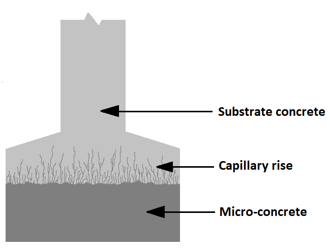
- The micro-concrete jacketing applied on the bottom face of the girders, was found to improve the microstructural quality of substrate concrete as well. The rebound hammer test post repairs showed high and improved values in the portion of the girders adjacent to the micro-concrete application. This may be attributed to the capillary ingress of cementitious solution from the micro-concrete into the substrate, thereby imparting a degree of performance improvement in addition to enhancing the bond strength between the substrate and RC jacket.
4.5 Shotcrete Application
- Surface Preparation: Piers with minimal distresses were cleaned and repaired as necessary by shotcrete.
- Application: Shotcrete was applied to provide a uniform and durable surface layer.
Advantages:
- Rapid Application: Shotcrete allows for quick application over large areas.
Durability: Provides a strong, cohesive layer that adheres well to the existing structure.
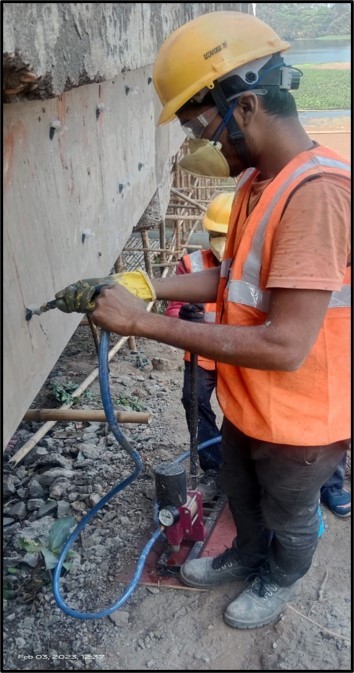
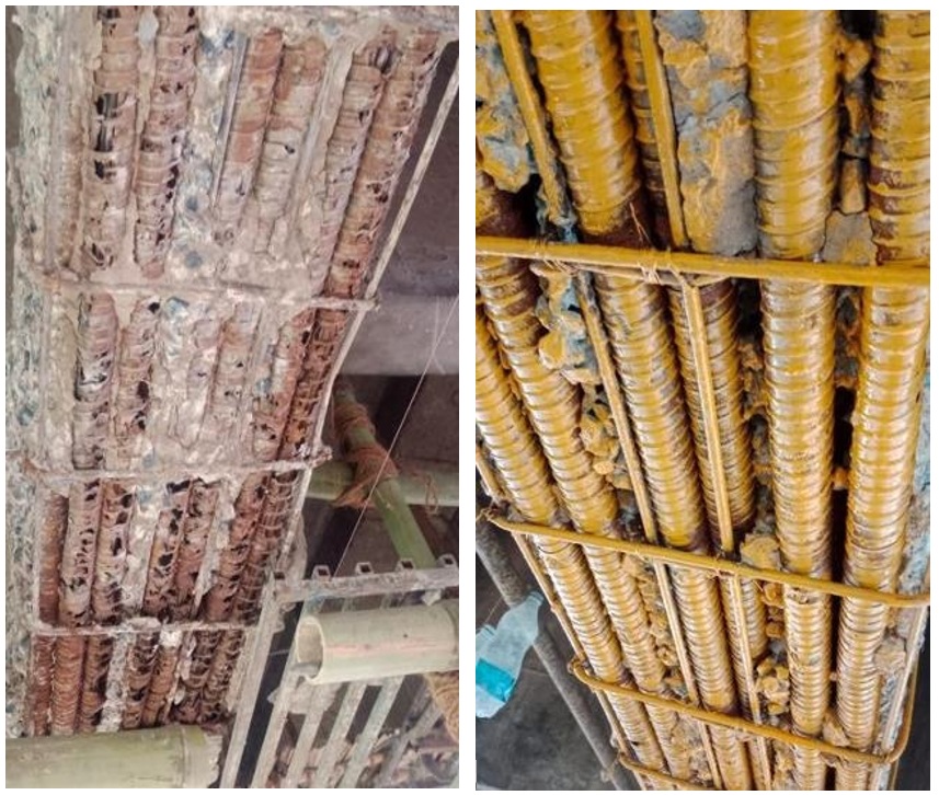
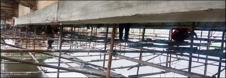
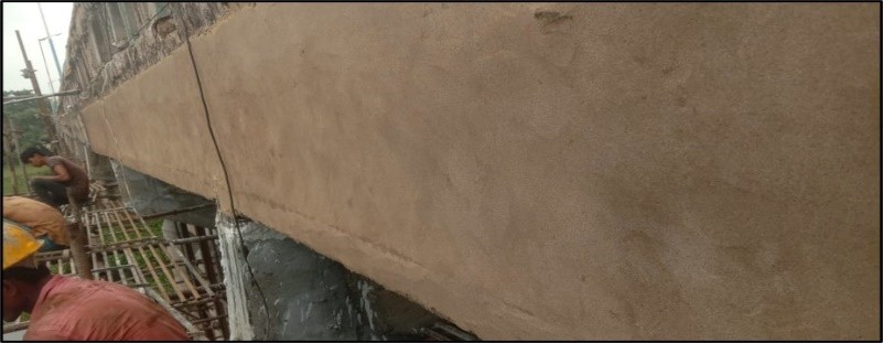
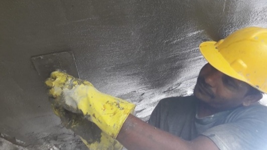
Photo 7 (a),(b) & (c): Building up of sectional area of structural members using a. epoxy mortar (top) b. polymer modified mortar (middle) c. micro-concrete (bottom)
5. STRENGTHENING & RETROFITTING METHODOLOGY:
It was thought for externally bonded FRP (Fibre-reinforced polymer) based strengthening measures because since 1980 it became popular for the retrofit of concrete structures in Europe and Japan. But in that case, the salient requirement was to meet the minimum strength criterion laid out by ACI-440-2R-17, which is one of the popular design guidelines used for designing FRP based strengthening measures for RC/PSC structures across the world. The criterion is as follows:
(∅𝑅𝑛)𝐸𝑥𝑖𝑠𝑡𝑖𝑛𝑔 ≥ (1.1𝑆𝐷𝐿 + 0.75𝑆𝐿𝐿)
Wherein, (∅𝑅𝑛) E𝑥𝑖𝑠𝑡𝑖𝑛𝑔 is un-strengthened structural member strength, 𝑆𝐷𝐿 is demand due to dead load and 𝑆𝐿𝐿 is demand due to live load.
Factored existing moment capacity of the member must be more than 1.1 times the moment due to dead load + 0.75 times the moment due to live load. This criterion is in place to protect the structure against sudden failures due to disconnection of FRP from concrete, which could occur due to any accident or vandalism. The same was checked for shear criteria as well.
Also, the alternative solution of external post tensioning was also thought to be implemented for which again a good concrete compressive strength and quality is prerequisite.
It was however observed that by improving the microstructure of the concrete and by performing repairs against the large honeycombed portions using high strength micro-concrete, cement grouting and epoxy grouting, appropriately done as per the need, the structural members could be made ready for FRP based strengthening methods. Like the soffit of the girders were repaired with micro concrete for rebuilding the sections, mainly the girders so that the CFRP(Carbon Fibre Reinforced Plastic) laminates can be placed on a smooth surface and to ensure proper transfer of stress between CFRP and the substrate.
Hence the following methodology was implemented.
5.1 Choice of material:
FRP Composite
A Fiber Reinforced Polymer (FRP) composite is defined as a polymer (plastic) matrix, either thermo set or thermoplastic, that is reinforced (combined) with a fibre or other reinforcing material with a sufficient aspect ratio (length to thickness) to provide a discernible reinforcing function in one or more directions. FRP composites are different from traditional construction materials such as steel or aluminium. FRP composites are anisotropic (properties apparent in the direction of the applied load) whereas steel or aluminium is isotropic (uniform properties in all directions, independent of applied load). Therefore, FRP composite properties are directional, meaning that the best mechanical properties are in the direction of the fibre placement. FRP composites are composed of:
- Epoxy – The primary functions of the resin are to transfer stress between the reinforcing fibres, act as a glue to hold the fibres together, and protect the fibres from mechanical and environmental damage. The most common resins used in the production of FRP grating are polyesters.
- Reinforcements – The primary function of fibres or reinforcements is to carry load along the length of the fibre to provide strength and stiffness in one direction. Reinforcements can be oriented to provide tailored properties in the direction of the loads imparted on the end product. The largest volume reinforcement is glass fibre.
- Fillers – Fillers are used to improve performance and reduce the cost of a composite by lowering compound cost of the significantly more expensive resin and imparting benefits as shrinkage control, surface smoothness, and crack resistance.
- Additives – Additives and modifier ingredients expand the usefulness of polymers, enhance their process ability, or extend product durability.
Composite materials are made by combining at least two different constituent materials with one or more materials as reinforcements, and one or more materials as the matrix. FRP composite is similar to Reinforced Concrete, with a fibre (such as glass, carbon or aramid) as the reinforcement and a polymer (polymer resin matrix such as epoxy, polyester) as the matrix. The fibre reinforcement carries load in pre-designed directions and the polymer matrix serves as a binder, a medium to transfer loads between adjacent fibres and to provide protection for the fibre. Current FRP composite materials typically have high strength and high-stiffness structural fibres embedded in lightweight, low-cost, and environmentally resistant polymers which have better mechanical and durability properties than either of the constituents alone. FRP products produced for use in structural engineering can comprise significantly more ingredients than just the primary constituents: fibre and polymer resins.
5.2 Advantages and limitations of FRP:
FRP especially CFRP has tremendous potential and has great advantages over conventional materials and techniques of retrofitting of RC structures. The increase in use of FRP for retrofitting of RC structure may be attributed to their advantageous properties mainly – high corrosion resistance, light weight, extremely high strength to weight ratio, ease of handling and installation (hence substantially reduced working time), no need for form work, less space occupancy and available in different sizes, dimension and geometry. However, there are some factors limiting its frequent use such as very high material cost, brittle failure, low fire resistance and lack of design codes on FRP in many countries like India, unawareness of or reluctance to accept existing reports, guidelines and technical publications currently being used worldwide.
FRP’s can be used in the concrete structures in following forms:
- Plates– at the face to improve the tension capacity.
- Laminates– below beams and slabs to improve load taking capacity.
- Bars– as reinforcements in beams and slabs replacing the steel bars
- Cables– can be used as tendons and post- tension members in suspension and bridge girders.
- Wraps– around concrete members i.e. columns, beams, slabs etc for confinement.
5.3 Strengthening Methodology in Details
The strength of the structure was estimated using NDT. The decreased prestressing steel area (with a rational and safe estimation of 25% decrease in area) and actual concrete area was then updated into the structural model created using the software Sofistik. The structural capacity was found to be sufficient to qualify the minimum strength criterion as per ACI-440-2R-17. Hence FRP based methods could be allowed to be applied.
When being placed at an effective depth of 2.4mt (bottom face of girder), the carbon laminates needed to generate 1417kN-m resisting moment (in Ultimate Limit State) so that it addresses the deficit between the existing strength and the design capacity required as per current IRC standards. This was checked using the updated Sofistik model. Accordingly, a retrofit design scheme was developed, (Figure 2) wherein the CFRP laminates could generate an 1417kNm factored ULS (Ultimate Limit State) moment capacity. These factors are for uncertainties inherent in FRP system which is based on reliability analysis which is 0.85 here and additional strength reduction factor depending upon tensile strain in steel at extreme tension which is derived at 0.9 in our case.
This ULS moment could be achieved by 10nos. 3mm thick 100mm wide CRFP laminates. The gross moment capacity for CRFP was calculated at 2115 kN-m, when factored as above as per ACI norms, the capacity reduces to 1499kN-m which is more that required ULS resisting moment of 1417kN-m, thereby making the design safe with sufficient reserve strength for compensating any variations in strength parameters between the model and the actual structure. The above moment was calculated when total tension at steel and FRP is balanced with total compression in concrete. While making trial to balance the tension and compression, debonding strain of FRP became failure mode. The considered Elastic modulus of FRP as per manufacturer’s specification 165 GPa during design. However, the material was tested at IIT Hyderabad and elastic modulus of 176 & 178 GPa was the test result. Similarly strain at peak load was considered as 1.3% on the other hand the test result at IIT Hyderabad is 1.58% and 1.6% which is satisfactory.
CFRP wraps as shown in Figure 2 which could increase the shear capacity of the girder by an unfactored capacity of 699kN, which reduced to 534kN as factored as mentioned above shear strength contribution (as specified in 440-2R-17 standards), thereby making the design safe in shear as well. SRM C Lam 100×3 carbon laminates were used to contribute flexural strengthening and SRM C Wrap UD 450 carbon wraps were provided to contribute the shear strength as shown in the figures below. The CFRP materials was sent to IIT, Hyderabad for testing and found to be alright.
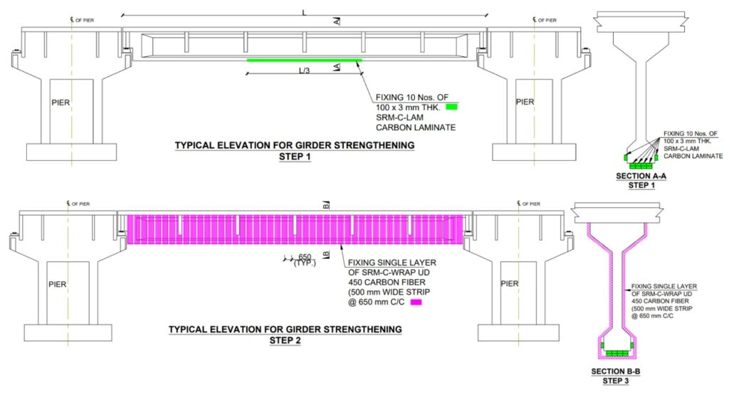
Application of CFRP for strengthening the structures primarily requires surface preparation. The repaired concrete surface was grinded to remove any protrusions and undulations. Any undulation felt was straightened using M40 grade structural putty as required. The structurally sound surface thus obtained was primed using a compatible primer. The laminates were installed first, along the markings made as per dimensions in the drawing. M40 grade structural adhesive was used to bond CFRP laminates to the concrete. Once fully cured, a layer of epoxy was applied and the wraps were installed as per drawing, using dry layup technique.
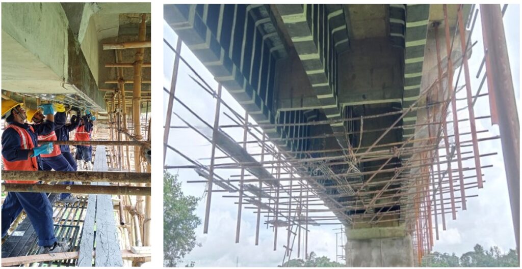
(a) The laminates were installed first, along the markings made as per dimensions in the drawing. M40 grade structural adhesive was used to bond CFRP laminates to the concrete.
(b) All sharp corners of the girder were grinded to at-least 25 mm radiuses so that the CFRP wrap used to enhance shear do not cut at the sharp edge of the girder. Once fully cured, a layer of epoxy was applied and the wraps were installed as per drawing, using dry layup technique. (Photo 8 a & b).
5.4 Structural Modelling and CFRP Design
Modeling:
- Finite Element Analysis (FEA): A detailed FEA model was created using software like Sofistik or SAP2000. The model incorporated dimension of the structural members, updated material properties, loading conditions, and boundary conditions.
Analysis of girder:
- Prestress Loss Analysis: The loss of prestress over time using historical data and design codes were used to arrive at the stress level at the girder and deck slab.
CFRP Design:
- Flexural Strengthening: CFRP laminates were designed to increase the flexural capacity of the girders. The design followed guidelines from ACI-440, focusing on the placement and orientation of CFRP strips.
- Shear Strengthening: CFRP wraps were applied around the girder sections to enhance shear capacity, designed according to shear strengthening protocols.
Allied applicational Considerations:
- Bonding Strength: Ensured that the bonding strength between CFRP and concrete met required safety margins.
- Environmental Durability: Considered exposure conditions to select appropriate CFRP types and protective coatings.
5.4 CFRP Application Process
- Surface preparation: Application of CFRP for strengthening the structures primarily requires surface preparation. The repaired concrete surface was grinded to remove any protrusions and undulations. All sharp corners were grinded to at-least 25mm radius to prevent stress concentration on CFRP.
- Primer application: Grinded surface was thoroughly cleaned with pressurized air for removing dust and loose materials. This structurally sound surface was then coated with SRM Primer, which is a two-part epoxy resin-based primer with low viscosity and rapid curing property. It has a pot-life of 40 minutes at room temperature and remains tacky for 6 hours. These periods reduce for higher temperatures.
- Putty application for pits and undulations: Any undulation or gaps felt was filled and levelled out using the SRM structural putty, which has M50 compressive strength. It is a two-component thixotropic epoxy-based putty, with adhesive bond strength of 3.5MPa with concrete. It has a pot-life of 30 mins at room temperature, hence must be applied and trowelled quickly. After 24 hours, the putty was sanded to obtain uniformly smooth surface.
- Laminate and SRM SA: As per drawing, the locations of laminate were marked on the putty surface. The laminates used were SRM-C-Lam 100×3, which is a carbon laminate with the cross-sectional dimension of 100mm x 3mm. These possess ultimate tensile strength as high as 1,500MPa with ultimate strain value of about 1.1%, implying that Youngs modulus of approximately 140GPa. If tested until failure, one such laminate could withstand up-to 450kN of tensile load. The density of the carbon laminate is 1.58g/cc. CFRP laminates therefore has high strength to weight ratio as compared to steel, which permits the usage of smaller sectional profiles to be used for strengthening. These lightweight materials are fast curing, non-corrosive and has good fatigue resistance as well. CFRP laminates such as these, are widely used to improve the flexural capacity of beams, girders, and slabs by application parallel to main rebars.
For application, exact length of laminate required was saw-cut, air-blown and cleaned with dry cloth. Further, the structural adhesive SRM SA was mixed. It is a two-component solvent-free, thixotropic, epoxy resin adhesive, which has 60MPa compressive strength when mixed in 3:1 ratio of base and hardener. Mixing was performed sufficiently to obtain uniform colour without air entrainment. One side of the previously cut SRM C Lam carbon laminate was applied with a 2mm layer of SRM SA and applied onto the marked surface on the concrete, ensuring no air gets in between, by repeated tapping.
- Primer + Saturant: At the locations where FRP application was required, another layer of primer was applied. Following the curing of primer, one layer of SRM Saturant was applied on the area of CFRP application. The saturant is also a two-component epoxy resin-based compound, which has pot-life of around 60 mins at room temperature and tensile strength of 20MPa.
- Two layers of CFRP Wrap: Slight excess of saturant was applied using brush at first and the CFRP wrap was pressed onto it in airtight manner using rollers. The CFRP used was SRM-C-Wrap UD450, which is a uni-directional, 0.25mm thick carbon fiber wrap, that has a tensile strength over 4,000 MPa and elastic modulus above 240MPa. Since the CFRP wrap is pure carbon fiber devoid of epoxy, the density is 1.8g/cc, which is higher than that of CFRP laminates. This CFRP weighs 450 grams per square meter when cut from the roll (450GSM). Like laminates, the wraps are also light weight, corrosion resistant, fast curing retrofitting materials. Since the carbon fibers are woven into fabric form, CFRP wraps can be applied even on cylindrically curved concrete surfaces such as piers, arched slabs, industrial chimneys, etc. These are regularly used for improving shear strength in girders, beams, and slabs; and for improving confinement of piers, columns, and other compression members. In this project, CFPR wraps were applied in two layers using dry layup technique, wherein the fibre was saturated by being pressed against the concrete substrate coated with the saturant. (Photo 8)
- Bond coat: For any cementitious protective coating to adhere on the CFRP system, a bond coat is required. An epoxy resin-based medium viscosity liquid based on Bisphenol-A was applied on the substrate and clean washed sand was pasted on it for mechanical keying with next layer.
- Guniting: The protective layer was created using shotcrete. Sika Sigunit Powder K + Cement + Sand + Stone dust in the mix ratio 1:2:2:2 was used, coupled with water addition as per the MSDS. Such mixes rebound less from the substrate and develop high early strength within the first 24 hours. The primary component complies with ASTM C 1141 Type 1 Grade 9 Class B. The gunited surface after curing, was coated with anti-carbonation coats for improved durability.
Inspection:
- Quality Checks: Post-application inspections were conducted using ultrasonic testing to check for voids and ensure proper bonding.
6. FULL SCALE LOAD TESTING:
For a structure which was once recommended to be demolished, any amount of theoretical proof would not suffice to overcome the psychological aspect of structural safety and serviceability. Full-scale load testing is perhaps the most convincing method to demonstrate the effectiveness of the repairs and strengthening methods applied on the structure, as the actual performance is verified by placing the actual factored design load on the structure. Methodology for the same has been laid out in IRC SP 37 and IRC SP 51.
Two spans were identified for load testing and loading scheme was calculated as per IRC norms for highway bridges. The bridge was designed for two lane IRC class-A or one lane class-AA load as at that time provision of Class 70R and special purpose vehicle was not there. Retrofitting was done to restore original capacity of the bridge for which the bridge was originally designed which was lost due to various reasons discussed in this paper.
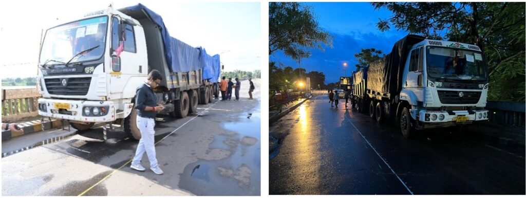
No capacity enhancement could be done. Analysis was carried out to find out the load type either two lane class-A or one lane class-AA load which one creates maximum bending moment. The load test was done by placing test load in such a position and intensity so that it can produce more or less same bending moment for which the bridge was designed. LVDTs (Linear Variable Differential Transducer) were placed at each quarter length of test girder. Load application was performed through loaded trucks (Photo 9). The girder was monitored for the first day without loads for temperature correction data, on 2nd day with load for finding the peak deflection and on 3rd day after removal of loads, for checking the percentage recovery. Load was applied in increments of 25%.
After temperature correction, the peak deflection was found to be 6.30mm, which is within the theoretical value from modelling. The acceptance criterion as per IRC is that the PSC bridge must recover at-least 85% of the deflection after removal of 100% of the loads, within 24 hours. The representative span under testing passed the full-scale load test with 92% recovery within 24 hours, thereby proving that the retrofitting measures were successful and the bridge was ready for traffic opening during August, 2023 with a bit of restriction for better safety against probable overloading of commercial vehicles.
7. CONCLUSION
Structural retrofitting is a practical solution to many such age-old bridges. Demolition and reconstruction of public infrastructure is cumbersome and has high societal and environmental impact, therefore shall be adopted only in extreme conditions after thorough investigations. Design guidelines and codes are meant to be utilized as powerful tools for enabling optimal decision making, through sound engineering practices. In this project, even when FRP based measures were doubtful as per the initial condition according to the criteria laid down in ACI 440, properly applied well-engineering repair techniques made the structure qualify for the same, which then lead to bringing the structure back to service through CFRP based strengthening measures.
The successful retrofitting of the Birendra Sasmal Setu Bridge demonstrates that even severely deteriorated structures can be effectively rehabilitated with modern techniques. The application of CFRP and other advanced materials significantly restored the bridge’s structural capacity and safety.
The authors would acknowledge the efforts made by Sri Partha Sarathi Dey, Astt. Chief Engineer, NH, PWD and Sri Arunavo Gupta, Executive Engineer, NH Design Division, PWD for their important inputs in this paper.
8. Way forward
The Indian guideline for such retrofitting of the bridge structures through FRP laminates and wrapping need to be formulated.
About Dr. Mangesh V. Joshi
Dr. Mangesh V. Joshi is the Founder and CEO of Sanrachana Group and holds a PhD from IIT Bombay, specializing in FRP for reinforced concrete. With experience across 2,500+ structural retrofitting projects in India and internationally, he is a recognized professional in structural strengthening and rehabilitation of civil engineering structures. He has 20+ publications in reputed platforms including Springer, IRC, ICI, IABSE and other technical journals, and has contributed to Dr. Raina’s book Bridges Past & Future. He is a member of the IRC 8.6 Committee, which is developing guidelines for FRP-based strengthening techniques for road bridges. He is also licensed with BMC, TMC and NMMC and has served on the Boards of Governors of institutions including IIT Roorkee, IIT Patna, NITTR Bhopal and VJTI Bombay, along with an advisory role at RCGSIDM, IIT Kharagpur. He is associated with professional organizations such as IRC, IC-ACI, Indian Institute of Engineers, Institute of Structural Engineers, Council for Tall Buildings and Urban Habitat, and PEATA India.
About Rajib Chattaraj
Rajib Chattaraj is the Chief Engineer at the Public Works Department (PWD), Government of West Bengal. Based in Kolkata, he has been serving as Chief Engineer since November 2021, following his earlier role as Superintending Engineer with PWD West Bengal. His professional experience spans public infrastructure, civil engineering and bridge-related works.
References:
- ACI-440-2R-17: American Concrete InstituteGuide for the Design and Construction of Externally Bonded FRP Systems for Strengthening Concrete Structures.
- IRC: 6 Code of Practice for Road Bridges, Load & load combinations.
- IRC: SP 37 Guideline for evaluation of load carrying capacity of bridges
- IRC: SP 51 Guideline for load testing of bridges.
- Internal Report of the technical consultant on Repair & Rehabilitation Work of Birendra Sasmol Setu – Kangsabati River Bridge
- Joshi, M.V. and Vivek, S.V., 2024. Retrofitting of RC Structures Using FRP Techniques—Case Studies. In RC Structures Strengthened with FRP for Earthquake Resistance (pp. 207-242). Singapore: Springer Nature Singapore.
- Joshi, M.V. and Vivek, S.V., 2023, December. Structural Retrofitting of Chitpore Bridge. In Structural Engineering Convention (pp. 25-35). Singapore: Springer Nature Singapore.
- Ingole, P., Gosavi, R.M. and Joshi, M.V., 2022. Structural repair and strengthening of road bridge across Savitri River at Ambet, Maharashtra. Indian Highways, Indian Roads Congress, May 2022 edition.