
Principal Consultant, Corrosion and Water Management Consultants & Ex-Additional General Manager (NETRA), NTPC
Recently many of the Reinforced Concrete structures in contact with water (both seawater and fresh water) have been observed to be suffering from Corrosion Induced damages. The damages observed are concrete cracking, spalling of concrete, efflorescence, water leakages, rust spots, rusted rebars, broken rebars, etc. Some of these defects have been observed within a short span of 3 years from the time of taking these structures in service. In some cases the damages have been observed after 15-20 years of service. However; the structures are required to be in service for another 20-30 years which means the structures need to be repaired & rehabilitated.
Prior to undertaking repair & rehabilitation activities, it is necessary to identify the reasons and extent of damage through detailed condition assessment of the structures. Based on the type and extent of damage, strategies for repair & rehabilitation of the structures need to be developed. The strategies need to include prevention/protection against corrosion for the expected life of the structures. These may include application of sealers, corrosion inhibitors, surface coatings; polymer modified concrete, cathodic protection/prevention, etc. A life cycle cost analysis is required to be carried out as some of these techniques may appear to be costly but considering the durability & life enhancement of the structures that can be achieved by employing the protection measure, the cost would be more than justified.
The present paper intends to present the details of investigations carried out on some of the structures along with recommendations for suitable repair & rehabilitation technique to be adopted. Some suggestions on enhancing the life/durability of the structures both during Repair & Rehabilitation and for new structures are also presented.
INTRODUCTION:
We generally think of concrete as a modern building material, yet it is one of the oldest and most durable building materials. Although the Romans experimented with bronze reinforcement, reinforced concrete as we know it today dates from the mid-19th century following the introduction of Portland cement concrete in 1854. Steel has the advantage of having the tensile strength that concrete lacks, and is highly compatible in its chemical and physical characteristics. The matching of thermal expansion coefficients is critical to the versatility of reinforced concrete.
Durable concrete is defined as concrete fit for the purpose for which it was intended, under the conditions to which the concrete is expected, and for the expected life during which the concrete is to remain in service.
ACI 201.2R Guide to Durable Concrete – “Durability of hydraulic cement concrete is determined by its ability to resist weathering action, chemical attack, abrasion, or any other process of deterioration”.
ACI 201 Deterioration Modes – Freezing & Thawing, Alkali-Aggregate Reaction (AAR), Chemical attack, Corrosion of embedded metal, abrasion.
Corrosion is one of the major modes of deterioration of concrete structures and is considered a big threat to the durability of the structures especially for structures in contact with water/seawater.
Concrete normally provides reinforcing steel with excellent corrosion protection. The high-alkaline environment in concrete creates a tightly adhering film that passivates the steel and protects it from corrosion. Because of concrete’s inherent protective attributes, corrosion of reinforcing steel does not occur in the majority of concrete elements or structures. Corrosion of steel, however, can occur if the concrete does not resist the ingress of corrosion-causing substances, the structure was not properly designed for the service environment, or the environment is not as anticipated or changes during the service life of the structure.
Concrete structures located in aggressive environments where high temperatures and high chloride levels exist in both natural soils and waters are subject to premature deterioration from corrosion of the reinforcement. Traditional methods of corrosion protection, such as concrete admixtures and passive barrier systems, may not be sufficient to provide the level of corrosion control needed for the intended design life. As a solution to this problem the use of cathodic protection (or cathodic prevention as it is called) at the time of construction is proposed. Although cathodic protection has been used as a rehabilitation method on existing salt-contaminated concrete structures for over 25 years, its application to new reinforced concrete structures is relatively new.
DETERIORATION OF RCC STRUCTURES:
Unexpected cracking of concrete is a frequent cause of complaints. Cracking can be the result of one or a combination of factors, such as drying shrinkage, thermal contraction, restraint (external or internal) to shortening, subgrade settlement, and applied loads. Cracking can be significantly reduced when the causes are taken into account and preventive steps are utilized. Deterioration of concrete occurs due to one or more of the following mechanisms (Table 1):
| S.No | Deterioration Mode | Typical Appearance |
|---|---|---|
| 1 | Structural Failure: Actual structural failure, or even structural cracking is only rarely encountered but it is important to differentiate between cracking from structural and other causes. | 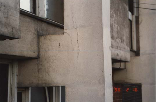 |
| 2 | Crazing is a pattern of fine cracks that do not penetrate much below the surface and are usually a cosmetic problem only. They are barely visible, except when the concrete is drying after the surface has been wet. |  |
| 3 | Plastic Shrinkage Cracking: When water evaporates from the surface of freshly placed concrete faster than it is replaced by bleed water, the surface concrete shrinks. Due to the restraint provided by the concrete below the drying surface layer, tensile stresses develop in the weak, stiffening plastic concrete, resulting in shallow cracks of varying depth. | 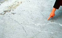 |
| 4 | Drying Shrinkage: Because almost all concrete is mixed with more water than is needed to hydrate the cement, much of the remaining water evaporates, causing the concrete to shrink. Restraint to shrinkage, provided by the subgrade, reinforcement, or another part of the structure, causes tensile stresses to develop in the hardened concrete. |  |
| 5 | D-cracking is a form of freeze-thaw deterioration that has been observed in some pavements after three or more years of service. Due to the natural accumulation of water in the base and subbase of pavements, the aggregate may eventually become saturated. Then with freezing and thawing cycles, cracking of the concrete starts in the saturated aggregate at the bottom of the slab and progresses upward until it reaches the wearing surface. | 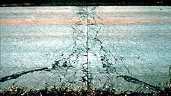 |
| 6 | Thermal cracks: Temperature rise (especially significant in mass concrete) results from the heat of hydration of cementitious materials. As the interior concrete increases in temperature and expands, the surface concrete may be cooling and contracting. This causes tensile stresses that may result in thermal cracks at the surface if the temperature differential between the surface and center is too great. |  |
| 7 | Corrosion of Steel: Steel reinforcement is normally chemically protected from corrosion by the alkaline nature of the concrete. If this alkalinity is lost through carbonation or if chlorides are present which can break down this immunity, then corrosion can occur. Obviously, when cover is low, the onset of corrosion will be sooner. |  |
| 8 | Alkali Silica Reaction: Alkali-aggregate reaction: Alkali-aggregate reactivity is a type of concrete deterioration that occurs when the active mineral constituents of some aggregates react with the alkali hydroxides in the concrete. Alkali-aggregate reactivity occurs in two forms—alkali-silica reaction (ASR) and alkali-carbonate reaction (ACR). Indications of the presence of alkali-aggregate reactivity may be a network of cracks, closed or spalling joints, or displacement of different portions of a structure. |  |
| 9 | Shrinkable Aggregates: Some, mostly igneous, aggregates can contain inclusions of weathered material in the form of clay minerals. These minerals, in common with the clays encountered in the ground, swell in the presence of moisture and shrink as they dry out. They can cause excessive drying shrinkage of the concrete and can cause a random crack pattern not unlike that encountered with ASR |  |
| 10 | Chemical Attack: Concrete buried in soils or groundwater containing high levels of sulfate salts, particularly in the form of sodium, potassium or magnesium salts, may be subjected to sulfate attack under damp conditions. As a guide, levels of sulfate above about 4% of cement (expressed as SO3) may indicate the possibility of sulfate attack, provided sufficient moisture is present. Sulfate attack requires prolonged exposure to damp conditions. | 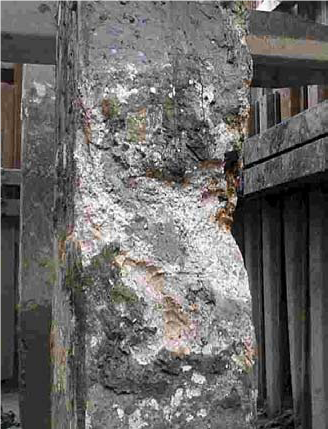 |
| 11 | Poor Quality Construction: During construction lack of attention to proper quality control can produce concrete which may be inferior in both durability and strength to that assumed by the designer. Particular factors in this respect are compaction, curing conditions, low cement content, incorrect aggregate grading, incorrect water cement ratio and inadequate cover to reinforcement. |  |
| 12 | Patch Accelerated Corrosion – Commonly referred to as “ring anode corrosion” or “halo effect”, patch accelerated corrosion is a phenomenon specific to concrete restoration projects. When repairs are completed on corrosion-damaged structures, abrupt changes in the concrete surrounding the reinforcing steel are created. Typical concrete repair procedures call for removal of the concrete around the full circumference of the reinforcing steel within the repair area, cleaning of corrosion by-products from the steel, and refilling the cavity with new chloride-free, high pH concrete. This procedure leaves the reinforcing steel embedded in adjacent environments with abruptly different corrosion potentials. This difference in corrosion potential (voltage) is the driving force for new corrosion sites to form in the surrounding contaminated concrete. The evidence of this activity is the presence of new concrete spalling adjacent to previously completed patch repairs. | 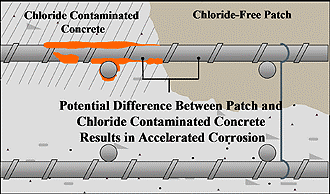 |
| 13 | Efflorescence: In chemistry, efflorescence (which means “to flower out” in French) is the loss of water or a solvent of crystallization from a hydrated or solvated salt to the atmosphere on exposure to air. On porous construction materials it may present a cosmetic problem only, but can sometimes indicate serious structural weakness. | 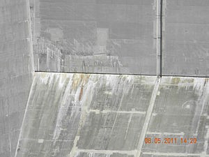 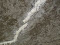 |
CORROSION OF REINFORCEMENT STEEL:
Whatever the source of deterioration and the mechanism of its development, corrosion of embedded reinforcement is recognized as the major problem affecting the durability of concrete structures. Reinforcing steel in good quality concrete does not corrode even if sufficient moisture and oxygen are available. This is due to the spontaneous formation of a thin protective oxide film (passive film) on the steel surface in the highly alkaline pore solution of the concrete. When sufficient chloride ions (from deicing salts or from sea water) have penetrated to the reinforcement or when the pH of the pore solution drops to low values due to carbonation, the protective film is destroyed and the reinforcing steel is depassivated.
When reinforcement corrodes, the corrosion products generally occupy considerably more volume than the steel. The magnitude of this increase in volume varies approximately 7 times the volume of the original material. As a result, the corrosion products produce an internal stress that destroys the neighbouring concrete under tensile stress.
Once corrosion is initiated, it is only a matter of time before the expansive pressures from steel oxidation causes concrete cracking, spalling and delaminations. If the on-going corrosion activity is not addressed, section loss of the reinforcing will occur and significant structure repair or replacement may eventually be required (Fig. 1).

t0 = the time for the environment to penetrate into the concrete to a level where corrosion starts
t1 = the time for the corrosion rate to increase to significant levels
t2 = the time for cracking to occur, and a subsequent further increase in corrosion rate
t3 = the time for significant structural distress to be caused
t0 will depend on quality of concrete and corrosive environment present
CORROSION PROCESS
Steel in concrete is normally protected from corrosion by a passive film of iron oxides on the steel surface resulting from the natural alkaline environment of the concrete. The passive film is chemically stable in the absence of carbonation and chloride ions. The ingress of chloride ions (Cl−) to the level of the steel reinforcing bars destroys the passive film and initiates corrosion. This makes reinforced concrete structures in coastal areas and/or marine environments vulnerable to damage by corrosion of steel reinforcement. Reinforced concrete infrastructures located in cold environments are also susceptible to corrosion damage due to the use of deicing salts. Carbonation penetrates concrete cover and destroys the passive film by neutralizing alkalinity of concrete. Once corrosion is initiated, electrochemical reactions occur, leading to the formation of expansive corrosion products that create tensile stresses in the concrete surrounding the corroding steel reinforcing bar. This results in concrete cracking and spalling, which aggravates the progressive damage, thus affecting the durability of the structure.
CAUSES OF CORROSION
Following are the two most common contributing factors leading to reinforcement corrosion:
(i) Localized breakdown of the passive film on the steel by chloride ions called chloride attack.
(ii) General breakdown of passivity by neutralization of the concrete, predominantly by reaction with atmospheric carbon dioxide called carbonation.
CARBONATION
Carbon dioxide, which is present in the air at around 0.3 per cent by volume, dissolves in water to form a mildly acidic solution. This forms within the pores of the concrete, here it reacts with the alkaline calcium hydroxide forming insoluble calcium carbonate. The pH value then drops from more than 12 to about 8.5.
In the case of carbonation, atmospheric carbon dioxide (CO2) reacts with pore water alkali according to the generalized reaction,
Ca(OH)2 + CO2 → CaCO3 + H2O
It consumes alkalinity and reduces pore water pH to the 8–9 range, where steel is no longer passive.
The carbonation process moves as a front through the concrete, on reaching the reinforcing steel, the passive layer decays when the pH value drops below 10.5. If the carbonated front penetrates sufficiently deeply into the concrete to intersect with the concrete reinforcement interface, protection is lost and, since both oxygen and moisture are available, the steel is likely to corrode. The extent of the advance of the carbonation front depends, to a considerable extent, on the porosity and permeability of the concrete and on the conditions of the exposure.
CHLORIDE
The passivity provided by the alkaline conditions can also be destroyed by the presence of chloride ions, even though a high level of alkalinity remains in the concrete. The chloride ion can locally de-passivate the metal and promote active metal dissolution. Chlorides react with the calcium aluminate and calcium aluminoferrite in the concrete to form insoluble calcium chloroaluminates and calcium chloroferrites in which the chloride is bound in non-active form. However, the reaction is never complete and some active soluble chloride always remains in equilibrium in the aqueous phase in the concrete.
MECHANISM OF CORROSION
The corrosion process that takes place in concrete is electrochemical in nature. Corrosion will result in the flow of electrons between anodic and cathodic sites on the rebar. For corrosion to occur, four basic elements are required:
- Anode – site where corrosion occurs and current flows from.
- Cathode – site where no corrosion occurs and current flows to.
- Electrolyte – a medium capable of conducting electric current by ionic current flow (i.e. soil, water or concrete).
- Metallic Path – connection between the anode and cathode, which allows current return and completes the circuit.
The anode is the location on a steel reinforcing bar where corrosion is taking place and metal is being lost. At the anode, iron atoms lose electrons to become iron ions (Fe+2). This oxidation reaction is referred to as the anodic reaction. The cathode is the location on a steel reinforcing bar where metal is not consumed. At the cathode, oxygen in the presence of water, accepts electrons to form hydroxyl ions (OH–). This reduction reaction is referred to as the cathodic reaction. The electrolyte is the medium that facilitates the flow of electrons (electric current) between the anode and the cathode. Concrete, when exposed to wet and dry cycles, has sufficient conductivity to serve as an electrolyte. Fig 2. illustrates the corrosion cell for a steel reinforcing bar embedded in concrete where the anode and the cathode are on the same steel reinforcing bar.

The corrosion of steel in concrete in the presence of oxygen but without chlorides takes place in several steps:
At the anode, iron is oxidized to the ferrous state and releases electrons
Fe → Fe2+ + 2e–
These electrons migrate to the cathode where they combine with water and oxygen to form hydroxyl ions
2e– + H2O + 1/2O2 → 2OH–
Fe2+ + 2OH– → Fe(OH)2
In the presence of water and oxygen, the ferrous hydroxide is further oxidized to form Fe2O3
4Fe(OH)2 + O2 + H2O → 4Fe(OH)3
2Fe(OH)3 → Fe2O3.2H2O
The anodic and cathodic reactions described above take place at the anode and the cathode, respectively. Currents flow through concrete from the cathode to anode by ion flow and through the reinforcing steel from the anode to the cathode by electron flow.
Two types of corrosion cells develop within concrete: microcells and macrocells. When a microcell develops within concrete, the anode is very close to the cathode on the same reinforcing bar as shown in figure. Carbonation-induced corrosion usually occurs on a microcell. When a macrocell develops, the anode and cathode are often well separated as shown in figure. Chloride-induced corrosion is prone to development of macrocells. The hydroxyl ions combine with the ferrous ions to form ferrous hydroxide (Fig. 3 & 4).


When carbon dioxide (CO2) from the atmosphere penetrates concrete and dissolves in the pore solution, carbonic acid is formed. This acid reacts with the alkali in the cement to form carbonates and to lower the pH of the concrete. When the alkalinity reaches a low enough level, the steel reinforcing bar becomes depassivated and in the presence of sufficient water and oxygen, corrosion is initiated and propagated.
The concentration of chlorides in concrete is not uniform due to the heterogeneity of the concrete. The chlorides enter the concrete from the exposed surface. These differences in chloride concentrations establish anodes and cathodes on individual steel bars and result in the formation of micro cells.
The corrosion of steel in concrete in the presence of chlorides, but with no oxygen (at the anode), takes place in several steps:
At the anode, iron reacts with chloride ions to form an intermediate soluble ironchloride complex
Fe + 2Cl– → (Fe2+ + 2Cl–) + 2e–
When the iron–chloride complex diffuses away from the bar to an area with higher pH and concentration of oxygen, it reacts with hydroxyl ions to form Fe(OH)2. This complex reacts with water to form ferrous hydroxide.
(Fe2+ + 2Cl–) + 2H2O + 2e– → Fe(OH)2 + 2H+ + 2Cl–
The hydrogen ions then combine with electrons to form hydrogen gas
2H+ + 2e– → H2
As in the case of corrosion of steel without chlorides, the ferrous hydroxide, in the presence of water and oxygen, is further oxidized to form Fe2O3
4Fe(OH)2 + O2 + H2O → 4Fe(OH)3
2Fe(OH)3 → Fe2O3.2H2O
The corrosion products resulting from the corrosion of steel reinforcing bars occupy a volume five to ten times that of the original steel. This increase in volume induces stresses in the concrete that result in cracks, delamination and spalls. If left untreated, the process continues which further accelerates the corrosion process by providing an easy pathway for water and chlorides to reach the steel until the concrete becomes structurally unsound as shown in Fig 5 & 6.


The minimum chloride ion concentration needed to initiate corrosion of steel reinforcing bars is also called the chloride threshold. Although the concept of chloride threshold is generally accepted, there is agreement on what the threshold value is. Several factors influence the chloride threshold value (Fig. 7 & Table 2): the composition of the concrete (resistivity), the amount of moisture present, and the atmospheric conditions (temperature and humidity). The threshold concentration depends on the pH level and the concentration of oxygen. Regardless of what concentration of chloride ions is needed to initiate corrosion, an increase in the chloride ion concentration increases the probability that corrosion of steel reinforcing bars will occur.

American Concrete Institute recommends the following limits for chloride in new constructions (ACI 222R-01)
| Category | Ch loride limits for New Constructions (% by Mass of Cement) | ||
| Test Method | |||
| Acid Soluble | Water Soluble | ||
| ASTM C 1152 | ASTM C 1218 | Soxhlet | |
| Prestressed Concrete | 0.08 | 0.06 | 0.06 |
| RCC in Wet Conditions | 0.10 | 0.08 | 0.08 |
| RCC in dry conditions | 0.20 | 0.15 | 0.15 |
Sulphate Attack:
Exposure category S – Concrete in contact with soil or water containing deleterious amounts of soluble sulphate
Four Classes:
- S0 – Very low exposure
- S1 – Structural member in contact with soluble sulphate (moderate) [seawater]
- S2 – Structural member in contact with soluble sulphate (severe)
- S3 – Structural member in contact with soluble sulphate : high sulphate content (very severe)
ACI Building Code 318: Sulphate Attack on Concrete
- Negligible attack: When the sulphate content is under 0.1 percent in soil, or under 150 ppm (mg/liter) in water, there shall be no restriction on the cement type and water/cement ratio.
- Moderate attack: When the sulphate content is 0.1 to 0.2 percent in soil, or 150 to 1500 ppm in water, ASTM Type II portland cement or portland pozzolana or portland slag cement shall be used, with less than an 0.5 water/cement ratio for normal-weight concrete.
- Severe attack: When the sulphate content is 0.2 to 2.00 percent in soil, or 1500 to 10,000 ppm in water, ASTM Type V portland cement, with less than an 0.45 water/cement ratio, shall be used.
- Very severe attack: When the sulphate content is over 2 percent in soil, or over 10,000 ppm in water, ASTM Type V cement plus a pozzolanic admixture shall be used, with less than a 0.45 water/cement ratio.
Effects of Rebar Corrosion:
There are several factors that that affect the corrosion process. The corrosion process leads to several coupled effects such as:
1. Longitudinal cracking of concrete cover due to expansive corrosion products.
2. Steel cross section reduction.
3. The degradation of steel–concrete bond.
As a result of these effects, the service life and the load-bearing capacity of reinforced concrete elements are considerably reduced. The corrosion rate is a key element in determining the time from corrosion initiation to corrosion cracking, which is usually used to predict the functional service life of a corroded RC structure. After corrosion initiation, the corrosion rate depends mainly on the availability of oxygen and moisture at the cathode and on the concrete resistivity, which is mainly affected by the internal moisture content and concrete porosity. Cooling towers host a perfect environment for the corrosion of embedded steel, and this deterioration affects several elements in the structure. Because products formed when steel corrodes occupy more space than the parent material, they exert significant tensile stresses on the concrete, causing unrestrained portions of the concrete mass to crack (Fig. 8). Cracking allows the further ingress of elements (such as chlorides and water) that fuel the corrosion process. As corrosion continues, delamination-a separation within the concrete that usually originates at the level of the reinforcement-occurs. Furthermore, spalling can occur along the deterioration curve.

DETERIORATIONS DUE TO AGGRESSIVE ENVIRONMENTAL CONDITIONS
High permeability concrete, poor design detailing, and construction defects, such as inadequate depth of cover, are quality control problems, which allow the ingress of salt and moisture into the concrete. The higher concentrations of salt and moisture can result in accelerated corrosion of the reinforcing steel and significant deterioration to the concrete structure.
Reinforced concrete structures that are partially or fully submerged in seawater are especially prone to reinforcing steel corrosion due to a variety of reasons. These include high chloride concentration levels from the seawater, wet/dry cycling of the concrete, high moisture content and oxygen availability. Three areas on concrete structures in marine environments can be distinguished regarding corrosion:
- The submerged zone (always below seawater);
- The splash and tidal zone (intermittently wet and dry); and
- The atmospheric zone (well above mean high tide and infrequently wetted).
The characteristics of the corrosion differ from one zone to another. The corrosion level on reinforced concrete structure located below water level is limited by low oxygen availability, and on the other hand lower chloride and moisture content in the atmospheric zone limit the corrosion level above high tide. Corrosion is most severe within the splash and tidal zones where alternate wetting and drying result in high chloride and oxygen content.
REMEDIAL STRATEGIES:
Corrosion Control Measures:
Epoxy-coated reinforcing steel — Epoxy-coated reinforcing bars have been widely used in aggressive environments since about 1973 and have generally met with success in delaying corrosion due to the ingress of chlorides. ASTM A 775 and AASHTO standard specifications were developed that outlined coating application and testing.
Galvanized steel — Galvanized steel has been used in concrete for the last 50 years, and is particularly appropriate for protecting concrete subjected to carbonation because zinc remains passivated to much lower levels of pH than does black steel. Unfortunately, zinc dissolves in a high pH solution with the evolution of hydrogen (H2) as the cathodic reaction The performance of galvanized bars significantly decreases if there is carbonation in the concrete surrounding these bars.
Stainless steel — Stainless steel is under investigation as a reinforcing material for structures in particularly aggressive environments. While ASTM A 304 stainless steel can tolerate higher amounts of chlorides, it is necessary to use the more expensive ASTM A 316L grade to gain significantly improved properties, particularly in bar mats of welded reinforcing steel
Cement and pozzolans — The components of the concrete that determine the pH of the pore solution, the total porosity, and the pore-size distribution are of importance for the corrosion process. In general, mineral admixtures such as fly ash, slag, and silica fume reduce and refine the porosity. Concretes containing these minerals exhibit considerably enhanced resistance to penetration of chlorides from the environment. The binding capacity of cement for chloride ions has been considered to be directly related to the C3A content of the cement. This is because the chloride ions can react to form insoluble chloroaluminates. The chloride ions, however, cannot be totally removed from solution by chemical binding. An equilibrium is always established between the bound and the free chloride ions, so that even with high C3A contents, there will always be some free chloride ions in solution.
Water-cementitious materials ratio — The porosity and the rate of penetration of deleterious species are directly related to the water-cementitious materials ratio (w/cm). For high-performance concretes, the ratio is generally less than 0.40 and can be as low as 0.30 with the use of suitable water-reducing admixtures
Aggregate — Unless it is porous, contaminated by chlorides, or both, the aggregate generally has little influence on the corrosion of reinforcing steel in concrete.
Curing conditions — The longer concrete is allowed to cure before being exposed to aggressive media, the better it resists penetration by chlorides or CO2. At an early age, fly ash concrete usually exhibits lower resistance to penetration of chlorides than an ordinary portland cement concrete, whereas at greater maturity, the fly ash concrete may have superior properties.
Corrosion inhibitors — A corrosion inhibitor for metal in concrete is a substance that reduces the corrosion of the metal without reducing the concentration of the corrosive agent. This is a paraphrase from the ISO definition (ISO 8044-89) of a corrosion inhibitor and is used to distinguish between a corrosion inhibitor and other additions to concrete that improve corrosion resistance by reducing chloride ingress into concrete. They can work either as anodic or cathodic inhibitors, or both, or as oxygen scavengers.
Cathodic protection — Cathodic protection of steel in concrete is a technique that has been demonstrated to be successful in appropriate applications in providing cost effective long term corrosion control for steel in concrete. Cathodic protection (CP) is the only known means of mitigating the corrosion of reinforcing steel, which is caused by the presence of the chloride ion in existing structures. It is a technique that requires specific design calculations and definition of installation procedures in order to be successfully implemented.
Condition Assessment of RCC Structures:
| Parameter | Test/Method |
| Concrete | |
| Compressive Strength | Rebound Hammer Windsor Probe Ultrasonic Pulse Velocity Core Capo Pull out Combination |
| Flexural Strength | Break-off |
| Direct Tensile Strength | Pull Off |
| Concrete quality, Homogenity, Honeycombing, Voids | Ultrasonic Pulse Velocity Pulse Echo Endoscopy Gamma ray radiography |
| Damages – Fire/Blast | Rebound Hammer Ultrasonic Pulse Velocity |
| Cracks – Pavements/Water Tanks | Ultrasonic Pulse Velocity Acoustic Crack detector Dye Penetration Test X –Ray Radiography Gamma Ray Radiography Thermal Imaging Crack Scope |
| Steel | |
| Location, Cover, Size | Rebar locator, Bar-sizer |
| Corrosion | Half-Cell Potential Resistivity Carbonation Chloride Content |
| Condition | Endoscope/Boroscope |
| Integrity & Performance | Tapping Pulse echo |
| S.No. | Potential (mV Vs Cu/CuS04) | Corrosion Condition | Electrical Resistivity (KiloOhm cm) | Corrosion Condition |
| 1 | > – 200 | Low | > 20 | Negligible |
| 2 | – 350 to – 200 | Intermediate | 10 to 20 | Low |
| 3 | < – 350 | High | 5 to 10 | High |
| 4 | < – 500 | Severe | < 5 | Very High |
SOME CASES OF DETERIORATION OF RCC STRUCTURES AT POWER PLANTS:
Chloride Induced Damages to Natural Draft Cooling Towers in Contact with Seawater:
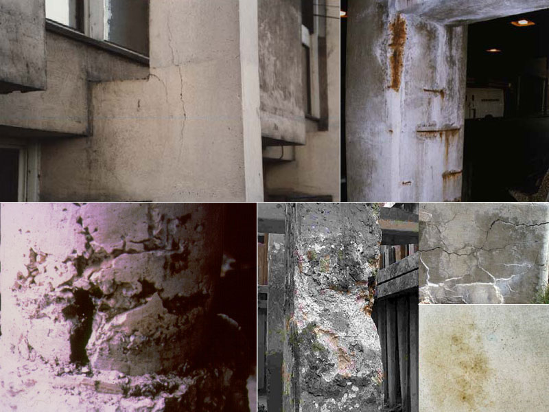
Natural Draft Cooling Towers at a station operating on seawater with 35000 ppm chloride were found to be suffering from corrosion induced damages such as spalling of concrete, rusted reinforced bars, cracks on the concrete, delaminated concrete, etc. Condition assessment of the structures was carried which included tests like core cutting & testing, depth of carbonation, rebound hammer tests, half-cell potential measurements, electrical resistivity measurements, etc. Subsequent inspection of the structure indicated that condition was deteriorating with time. The condition assessment data indicates: half-cell potential values lie between – 165 to – 550 mv Vs. Cu/CuSO4 and most of these values are more negative than – 200 mv suggesting severe corrosion of reinforcement bars; the resistivity values were between 0.4 – 26 kiloohms.cm & most of the values are much lower than 20 kiloohm.cm again suggesting severe corrosion of rebars; Chloride content is between 0.03 to 0.8% by weight of cement suggesting high chloride contamination of concrete and the pH values lie between 8.0 to 12.5 suggesting some chemical attack on concrete. Rebound hammer & core tests showed that there was some deterioration of concrete strength.
Recommendations were given for application of impressed current cathodic protection system along with patch repairs as chloride contamination had penetrated beyond rebars and patch repairs cannot take care of chloride contamination unless total contaminated concrete is removed and fresh chloride free concrete is applied.


Condition assessment of NDCTs


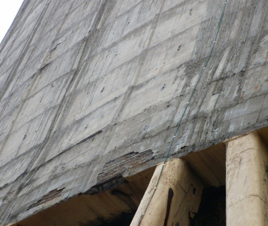
Some damages to raker columns were observed, these were repaired by patch repair. Observations after about 2 years indicated that damages have resurfaced suggesting patch repairs alone are not suited for highly chloride contaminated RCC structures.


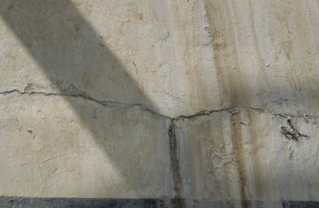
Carbonation Induced Damages to Induced Draft Cooling Towers in Contact with Fresh Water:
A station operating on fresh water as cooling water for more than 15 years reported some damages like cracks, spalling, delamination, etc of concrete structures of Induced Draft Cooling Towers. Preliminary condition assessment by half-cell potential and carbonation tests indicated that the potential values are between – 186 to – 293 mv Vs Cu/CuSO4 indicating that corrosion attack is low to high. Carbonation tests indicated severe carbonation/chemical attack (plant uses sulphuric acid for pH/alkalinity control in the cooling water system). It was inferred that most of the damages were on account of carbonation/chemical attack.
Recommendations were given for patch repairs followed by anticorrosive coatings on complete surfaces of water/water vapour touched surfaces of cooling towers for long term protection. For helping in long term durability of the structures, sacrificial cathodic protection can be employed.


REPAIR AND REHABILITATION OF DAMAGED RCC STRUCTURES:
Repair & Rehabilitation of Damaged RCC Structures:
To repair is defined as “to replace or refix parts, compensating for loss or exhaustion”. One definition of the word rehabilitate is “to restore to proper condition”. These definitions are worth bearing in mind. If we want to rehabilitate a structure we want to restore it, not necessarily to its original condition, because if we do, it may fail again because of intrinsic flaws. We want to establish its “proper” condition that is, resistant to corrosion. In other words, to rehabilitate the structure we may need to improve it compared to its original condition. To repair is merely fixing the damage. This implies that deterioration may continue. Patch repairs are just what they say. They repair the damaged concrete. They will not stop future deterioration and may accelerate it. Cathodic protection and other electrochemical techniques can rehabilitate the structure. They mitigate the corrosion process across the whole treated areas. Coatings and barriers can also rehabilitate if applied well at the correct time.
Patch Repair:
By far the most common repair technique is the application of concrete patches to damaged or deteriorated concrete. Furthermore, when other remediation techniques are being applied in order to limit the extent of on-going corrosion mechanisms or to prevent their re-occurrence. Patch repairs are also used to reinstate the spalled or delaminated areas of concrete.
Electrochemical Process:
Conventional patch repair is, and will always remain the primary method of repair of reinforced concrete structures suffering from corrosion damage to the reinforcement. Electrochemical techniques provide a useful set of methods for preventing or limiting further damage to structures affected by reinforcement corrosion.
- Cathodic Protection (CP): In cathodic protection, the corroding anodic areas of steel are made cathodic by the supply of electrons from an anode applied either to the concrete surface or embedded. There are two ways of applying cathodic protection to structures: Galvanic and Impressed Current CP
- Electrochemical Chloride Acceleration (ECE) – is also known as desalination or chloride extraction (CE). The fundamental principle involved in ECE is similar to that of CP. The only major differences are the period and level of current application. CP is essentially a permanent installation involving an application of current in the region of 5-20 mA/m2 of steel whilst ECE is a temporary treatment where a much higher current density in the range of 0.5-2.0 A/m2 of steel is applied over a period of weeks. The chloride ions migrate to the concrete surface where they are removed.
- Electrochemical Re-alkalization is used for carbonated reinforced concrete structures and entails the re-establishment of alkalinity around the reinforcement and in the cover zone. Alkali ions are electrically driven toward the steel which, with the production of hydroxyl ions at the steel, repassivate the steel and reduce corrosion activity to a negligible level. The electrolyte is highly alkaline and drawn into the carbonated cover concrete by electro-osmosis where it acts as a buffer zone. This process is applied as a single treatment taking a few days for each zone treated.
Corrosion Inhibitors
Corrosion Inhibitors are one of a variety of techniques that can be employed in an effort to suppress and control the rate of steel corrosion in concrete structures particularly in the case of hidden or latent damage, although their long term effectiveness in reinforced concrete is still open to debate and the subject of detailed research. Due to the large number of commercially available concrete corrosion inhibitors, which vary widely in their respective formulations and inhibitive properties, categorisation is difficult. However, it is possible to divide concrete corrosion inhibitors into two generic categories.
- Concrete admixture inhibitors – used as a preventative measure.Surface applied and drilled-in inhibitors – used as a curative or preventative measure.
These two generic categories can be further subdivided into anodic, cathodic and ambiodic (mixed) inhibitors depending upon the formulation of the inhibitor.
Surface Treatments:
Three generic types of Surface Treatment are available for the decoration and protection of concrete surfaces, designed to control chemical ingress as well as moisture movement. They are described as follows:
- Pore-liners – these are hydrophobic impregnation treatments such as silicone impregnants, which line the pores of concrete. They repel water and therefore prevent it from entering the concrete, but continue to allow water vapour to escape.
- Pore blockers – these are materials that partially or completely block the in concrete. They may accomplish this by either reacting with the concrete to produce pore-blocking products or by physically blocking the pores.
- Film-formers – these are coating systems based on either organic resins such as styrene butadiene and acrylic copolymers or inorganic resins such as potassium silicate, which form a protective/decorative film on the surface of the concrete.
Coatings may be endowed with special properties, such as the ability to bridge moving cracks whilst maintaining film integrity.
Using Cathodic Protection to Control Corrosion of Concrete Infrastructure in Marine Environments:
Traditional methods of repairs, such as removing deteriorated concrete and replacing with concrete repair mortar, may not be sufficient to slow down the corrosion process to a point where the deterioration rate of concrete is significant. Structures in marine environment that are repaired with conventional methods may develop concrete damage in a short time frame due to the aggressive nature of on-going corrosion process.
Over the last fifteen years, cathodic protection has increasingly been used to provide cost effective corrosion control for reinforced concrete structures in marine environments. Both galvanic & Impressed Current Cathodic Protection systems have been used for this purpose.
About the author
The author has over 45 years experience in Corrosion Analysis, Control & Monitoring; Environmental Studies; Water Management; Planning & Monitoring of Research activities of Power Sector both within India and in Countries like UAE, Oman, Morocco, Egypt, Vietnam, South Africa, Bahrain, Iran, Uzbekistan KSA, etc
His specialties include, Corrosion failure analysis; Development of Cooling water Treatment Programs; Water Management; Cathodic Protection; Coating Selection and Specifications ; Corrosion Monitoring; Corrosion Audit with particular reference to seawater based systems, Power Plant Chemistry, Chemical Cleaning etc.
REFERENCES:
- “Protection of Metals in Concrete Against Corrosion”, ACI 222R-01,
- “Standard Practice – Inspection Methods for Corrosion Evaluation of Conventionally Reinforced Concrete Structures”
- “Corrosion of Reinforced Concrete: Advances in Remedial Treatments by Cathodic Protection”
- “Standard Test Method – Testing of Embeddable Impressed Current Anodes for Use in Cathodic Protection of Atmospherically Exposed Steel-Reinforced Concrete
- “Long-Term Effectiveness of Cathodic Protection Systems on Highway Structures”,
- “Electrochemical Realkalization of Steel-Reinforced Concrete—A State-of-the-Art Report”
- “Remediating corrosion in hyperbolic towers”, Kostas Demadis, Power
- “Cathodic protection of steel in concrete”,
- “Three myths about Corrosion of Steel in Concrete
- “Cathodic Protection of RCC Structures in Netherlands; Experience and developments”
- “Understanding Corrosion and Cathodic Protection of Reinforced Concrete Structures”, Internal Communication from Corrpro Cos.
- “Effects of cathodic prevention on the chloride threshold for steel corrosion in concrete”
- “How to prevent silo failure with routine inspections and proper repairs”, John W Carson & Richard T. Jenkyn, Powder & Bulk Engineering,
- “SILO FAILURES: WHY DO THEY HAPPEN?”, John W Carson & Tracy Holmes
- “Using Cathodic Protection to Control Corrosion of Concrete Infrastructure in Marine Environments”, Funahashi, Miki, MUI International.
- “Corrosion of Steel in Concrete – Understanding, Investigation and Repair”, John P Broomfield.
- Reports from FHWA & SHRP
- “REHABILITATION OF REINFORCED CONCRETE COOLING TOWER IN PETROCHEMICAL PLANT”, Zia Chaudhary, NACE International.


Comments are closed.