A façade panel that looks flawless in the rendering can still become a headache on the shop floor. The corner radius is too tight, a hole sits too close to a bend, or the flat pattern needs a sheet size nobody stocks. Architectural sheet metal is unforgiving that way: it is visible, repeated across hundreds of identical parts, and small errors multiply.
Design for manufacturability (DFM) closes the gap between design intent and what a press brake, laser, or punch can actually deliver. Applied early, it protects the look, the schedule, and the budget.
Why architectural work raises the stakes
Industrial sheet metal parts usually hide inside a housing. Architectural components are seen up close and in raking light, where oil-canning, tool marks, and inconsistent bends show immediately. Three things raise the stakes:
- Appearance is part of the spec. Finish, grain direction, and seam alignment matter as much as dimensions.
- Scale and repetition. One bad detail is copied across the whole project.
- Tight coordination. Panels must meet structure, glazing, and neighbors with real-world tolerances.
Core DFM principles
Match thickness to the job. Thin gauges oil-can on large flat areas, while thick material limits bend radii and raises cost. Choose the thinnest gauge that stays flat under wind load and handling, and add stiffening returns or ribs instead of going thicker.
Respect bend radius. As a rule of thumb, the inside radius should be at least the material thickness, more for harder alloys. Tighter radii risk cracking and visible stress marks. One consistent radius across a project reduces tool changes and cost.
Keep features away from bends. Holes and slots too close to a bend distort as the metal stretches. Leave a clear distance of a few material thicknesses, or add relief.
Add reliefs at bends and corners. Small relief cuts prevent tearing and bulging and let flanges fold cleanly.
Design for the sheet. Panel sizes that nest well on standard sheets cut scrap and cost, and let you place seams deliberately.
Control grain direction. Brushed and anodized finishes show direction, so specify it consistently so adjacent panels read as one surface.
Set realistic tolerances. Bending accumulates error. Hold tight tolerances only at joints and attachment points, and use slotted holes or adjustable fixings to absorb site variation.
Allow for movement. Metal expands and contracts with temperature, so detail fixings that let panels move instead of buckling.
Material and finish
Aluminum is light and forgiving, stainless is strong but springs back more, and copper and zinc develop patinas that change the look over time. Decide the finish early, since coatings add thickness and can affect fit at joints. Avoid contact between dissimilar metals to prevent galvanic corrosion.
Prototype before you commit
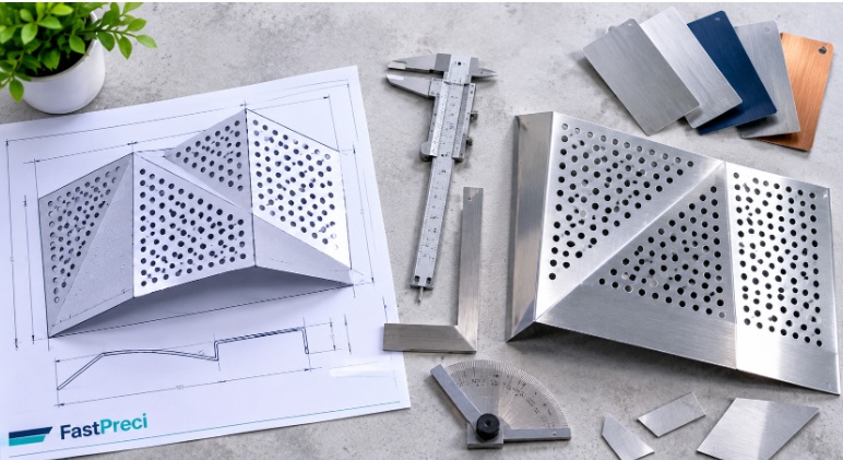
A physical mockup of one panel can reveal fit, seam, finish, and bend problems that drawings miss. Understanding sheet metal prototype design considerations, such as material behavior and bend allowances, helps you get useful results from fewer iterations.
Bring the fabricator in early
The cheapest time to fix a manufacturability problem is before drawings are final. Share models during design development and ask what the shop’s tooling can do. A partner offering custom sheet metal fabrication lets you move from prototype to production with the same team, so lessons from the mockup carry into the final parts.
Quick checklist
- Is the gauge right for panel size and loads?
- Are bend radii consistent and suited to the alloy?
- Are holes and slots clear of bend zones?
- Do bends and corners have reliefs?
- Do panels nest well on standard sheets?
- Is grain direction specified?
- Are finish thickness and tolerance stack-up accounted for?
- Has a mockup been reviewed?
The bottom line
DFM isn’t a constraint on creativity. It is what lets a bold detail survive the trip from rendering to façade intact, on time and on budget.