The collapse of two I-girders during ongoing metro construction at Ramapuram, Chennai, on June 13, 2025, has drawn attention to the structural practices governing temporary support systems used during girder erection. The girders, placed a week earlier as part of Corridor 4 of the Chennai Metro Phase II project, fell from temporary A-frame supports onto Mount Poonamallee Road, leading to the death of a motorcyclist. This incident prompted the metro authority to initiate an immediate review of all staging and support systems under execution in the corridor.
Metro viaduct construction involves handling large prefabricated elements in confined urban spaces with active traffic movement and limited working hours. In this context, temporary arrangements like A-frames, bearings, and braces act as the only support until permanent fixations are cast. However, while detailed procedures exist for permanent works, temporary systems are often treated as secondary—resulting in inconsistent standards, insufficient verification, and higher risk of failure.
This featured article presents key structural engineering and construction practices that must be adopted for safe I-girder erection. It identifies observed failure patterns from the Ramapuram incident and similar events, and recommends procedural safeguards to improve reliability during this pivotal phase of metro construction.
Collapse Event and Technical Observations
The two I-girders that collapsed near L&T’s head office were part of a viaduct segment between Porur and Alwarpet on Corridor 4. Each girder, weighing approximately 50–100 tonnes, had been installed on A-frame supports a week earlier. These frames serve as temporary supports until permanent bearings and diaphragms are cast and cured. According to CMRL’s preliminary report, one A-frame slipped or failed, causing both girders to topple and fall to the ground.
CMRL confirmed that diaphragm casting had not yet taken place, which means the girders were in an unsecured intermediate state. Debris clearance operations and partial traffic restoration followed, but structural investigation teams were mobilized to assess design and erection procedures.
Structural Role of I-Girders in Metro Viaducts
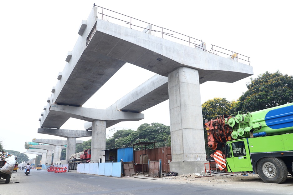
I-girders are longitudinal structural members used in the construction of elevated corridors. Their purpose is to span between piers and transfer deck loads to substructures. The typical erection method involves lifting these girders into position using cranes, temporarily supporting them, and then fixing them through bearing placement and diaphragm construction.
In elevated metro corridors, I-girders transfer loads from the deck slab to piers and piers to foundations. During erection, they must remain stable while bearing their own weight, withstanding minor dynamic loads from nearby activity, and awaiting integration into the full superstructure. The period between girder placement and diaphragm casting is a particularly vulnerable phase. Temporary systems like A-frames, bearings, and braces must resist not only dead load but also wind, vibration, and uneven settlements. Even short-term exposure in busy urban corridors can be a source of risk.
I-girders also face torsional forces before diaphragm casting due to cantilevering and lack of composite action with the deck. This requires restraint against both longitudinal translation and transverse rotation. Bracing must counteract these tendencies and reduce deformation until the structure becomes monolithic.
Common Failure Mechanisms in Girder Erection
Several recurring causes have been identified:
- Unstable A-Frame Supports: Inadequate design, faulty fabrication, or poor anchoring leads to support buckling or lateral movement.
- Improper Bearing Positioning: Misalignment causes unbalanced girder seating, increasing the chance of tilt or displacement.
- Delayed Integration of Girders: Failure to schedule diaphragm casting within the structural window prolongs vulnerability.
- Premature Support Removal: Uncoordinated disassembly or unlocking compromises stability.
- Vibrational Disturbances: External activity or wind can cause shifts if the girder is unrestrained.
- Incorrect Sequencing: Erecting spans in isolation or without balancing loads induces rotation or uneven settlement.
- Soil Movement at Base: Crane load, rainwater ingress, or poor soil compaction shifts base plates and alters alignment.

Structural Practices for Safe I-Girder Erection
1. Engineering Design of Temporary Works
- A-frames, base plates, and temporary bracing must be designed using comprehensive structural analysis.
- Load cases must include self-weight, crane load, wind load, and accidental load during erection.
- Fabrication drawings must reflect tolerances and detailing consistent with load transfer paths.
- Designs should be endorsed by certified professionals and verified through peer review.
2. Ground Condition Verification and Anchorage Systems
- Soil bearing capacity and compaction levels must be checked through tests at each support location.
- Where necessary, pile inserts, concrete pads, or spread foundations should be used.
- Anchor bolts should be torqued as per specification, and base shoes fitted with slip-resistant features.
- Waterlogging or settlement-prone areas should be identified through pre-construction surveys.
3. Sequence Planning and Diaphragm Casting Timeline
- Girder placement must be linked to diaphragm formwork readiness and casting window.
- Adjacent spans must be staged concurrently when sharing a common pier.
- Improperly staged ends can cause uplift or unbalanced rotation during later placement.
- Traffic impact zones should be assessed for dynamic loads during the temporary stage.
4. Locking and Bracing Measures Post-Erection
- Locking systems must engage longitudinal restraint immediately after girder seating.
- Transverse bracing should resist wind and eccentric crane movements.
- Restraint elements must remain in place until diaphragm concrete gains required strength.
- All restraint components should be tagged, logged, and tracked until removal is authorized.
5. Continuous Monitoring of Temporary Systems
- Inclination sensors and deflection meters should log movements beyond tolerance.
- Data should be recorded hourly and linked to control room dashboards.
- Strain gauges on A-frame members should trigger alerts if thresholds are exceeded.
- Monitoring should be carried out until diaphragm strength is achieved and verified.
6. Structural Review and Documentation
- Third-party reviews must validate that staging systems conform to design drawings.
- Erection plans should include checklists for bracing installation and crane placement.
- Engineers not connected to execution teams should authorize each erection stage.
- All approvals must be documented and archived in the project QA system.
7. Site Team Training and Supervision Protocols
- Personnel should be trained in girder balance, restraint points, and base inspection.
- Supervisors must carry updated drawings and stage-wise protocols.
- Daily tool-box meetings must include reminders on lock placement and bracing checks.
- Non-compliance should be logged and addressed with immediate corrective action.

Recommendations for Project-Level Oversight
- Metro authorities must implement a system-wide registry for all temporary works.
- Third-party audits should be carried out every fortnight for staging in live corridors.
- Any deviation from method statements must be reported and approved before continuation.
- Safety records of vendors and subcontractors should influence work allocation.
- Structural risk assessments should be part of bid evaluation and detailed project reports.
Conclusion
The Ramapuram collapse highlights the dangers posed by lapses in the design and execution of temporary structural supports during metro construction. These failures are avoidable when temporary works are given the same engineering rigour and oversight as permanent structures. As urban transit infrastructure projects grow in scale and complexity, there is a pressing need to implement a mandatory framework governing staging protocols, erection sequences, and site supervision practices.
Structural safety depends not only on sound design but also on coordinated execution. Standardized practices, reliable monitoring, and formal accountability are necessary to prevent repeat incidents. The findings from the Ramapuram investigation must lead to enforceable updates in construction protocols, ensuring safer metro construction environments across all urban corridors.
Image Source: kecrpg.com, knocksense.com, metrorailnews.in