Terrain Infratech takes ownership of their work. They unfailingly meet high standards of quality in both what they do and the way they do it. The company is committed to delivering the best Geosynthetic solutions. The company is constantly working on identifying, addressing and responding to the specific needs of each client maximizing value for money through their technical expertise. They have a healthy desire to stretch, to achieve organizational goals and accelerate business growth.
Products
TERRAINDRAIN (Geocomposite)
TERRAINCELL (Geocell)
TERRAINMAT (Coir Mat)
TERRAINNET (High Strength Wire Rope Panels for Rockfall Protection)
TERRAINTEX (Woven & Non Woven Geotextile Made from PET & PP Fibre)
TERRAINNAIL (Soil Nailing & Rock Nailing for Global Stability)
TERRAINBIAXIAL (Biaxial GEOGRIDS)
TERRAINROADCELL (Low Cost GEOCELL for PMGSY & Internal Roads)
TERRAINBAGS (Woven & Non Woven Geobags Made from PET & PP Fibre)
TERRAINCB( W-Beam Crash Barrier)
TERRAINGLASSGRID (Glassgrid for Pavements)
TERRAINCONCMATTRESS (Concrete Filled Mattress)
TERRAINGABIONS (Gabion Products)
TERRAINGEOMEMBRANE (Geomembrane)
TERRAINSTRIP (Polymeric Strips Reinforcement)
TERRAINUNIAXIAL (Uniaxial GEOGRIDS)
TERRAINEROSIONNET (HDPE GEONET for Erosion Protection)
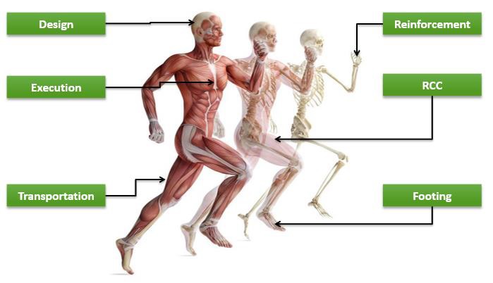
There are a number of similarities between a Human Body and an RCC Structure, from structural elements that form the load bearing system, to working as a homogenous member (form and function). Both are engineered to handle compressive and tensile stresses, impact load and vibrations, and many more forces that try to change the equilibrium of the system.
To increase the longevity (service life) of either of them, periodic health checkups or condition survey need to be carried out. A comprehensive condition survey may it be visual inspection or field testing, provides crucial data regarding the distress / deficiency.
If case history of a patient / structure is not available, primary step is to generate one. It is critical to approach a Civil Engineering Specialist(s) with domain knowledge and experience in Condition Assessment. As each patient is different, like wise each structure is different, and the tests to be carried out may vary. It is important to know,
Phase 1 – What to inspect?
Phase 2 – When to inspect?
Phase 3 – How to inspect?
Phase 4 – What to report?
Phase 5 – How to report?
Phase 3 comprises of visual inspection and field / lab testing. A holistic visual inspection is carried out to record all visible distress and other related aspects of the structure. Field / laboratory testing is narrowed down to necessary tests that provide the best data that can be converted into actionable information. Some of the common tests are,
Rebound Hammer Test
Ultrasonic Pulse Velocity Test
Cover meter Test
Concrete Core Test
Carbonation Test
Steel Ultrasonic Thickness Test and more
Once the structure case history and current condition survey report is available, corrective actions if any can be finalized and initiated, whether maintenance or major infrequent repairs. This exercise of a holistic approach to regular health checkup leads to huge economic savings and a more sustainable conscious society.
Author:
Sharad R. Pothnis
Sr. Vice President, Marketing and Innovation
Retrofitting and Repair Consulting Services Pvt Ltd
Liquid applied coatings systems fail for a number of reasons.
Most are due to incorrect installation practices or misunderstanding of the
performance capabilities of the system. One common application fault, occurs
when the required membrane film thicknesses are not achieved. Many think that
this is a sales pitch from membrane and adhesive manufacturers, to sell more
products
Three issues could arise when applying waterproofing membranes
below or above a mortar screed:
Abrasive damage to the coatings.
Elongation and flexibility restriction.
Re-emulsification of water basedcoatings.
All three of the above are affected by the coating film
thickness.
Film thickness and coating failure
Coating materials need to be abrasive resistant and accommodate
building movement. Quite often this is misunderstood and unbonded screeds are
placed over membranes that are applied too thin, resulting in mechanical
abrasion. This mechanical abrasion is akin to trying to wear through the coating
with a brick. Any thin spots, weak points or high spots can wear through,
forming ruptures and blisters.
Differential movement when sticking the tiles directly to the
coating will also impart mechanical abrasive stress at the coating interface,
especially with external applications. Waterproofing systems are subjected to
thermal shock movement and cyclic movement through saturation and drying
phases. Maintaining an even coat of coating Dry Film Thickness (DFT), reduces
the risk of abrasive blisters forming at thin spots and high points.
Movement accommodation at bond breaker junctions is severely
compromised when waterproofing is applied beneath a screed. The compacted
screed restricts the coating movement when releasing from the bond breaker, as
there is no active release zone. This can be addressed by installing
compressible foam rod to the perimeters, prior to placing the screed. This is
further compromised when the required DFT is not achieved, reducing the
membrane elongation tolerance drastically.
AS4858 Wet Area Membranes requires that a waterproofing system
must accommodate an average building movement of 5mm at joints and junctions. A
Class 3 coating has an elongation tolerance of above 300%, at the correct DFT.
Twelve millimetres of an even DFT will stretch another 36mm before elongation
failure. This sounds a lot, and your building is probably rolling down the hill
where 36mm of movement occurs, however the same membrane at half or less film
thickness may be struggling to stretch to 5mm.
Image Source: http://houseunderconstruction.com
Uneven film thickness is even more prone to elongation failure.
Thicker coatings can restrict movement, where thinner applied coatings will
tear under minimal movement. This is why filleting is not as successful as bond
breaker systems. An even DFT of coating, bonded to a compatible joint sealant,
is restricted from stretching as the uneven fillet section of sealant allows
free movement at the thin points, and restricts movement at thicker fillet
zones. Most flexible fillet systems are only aiming at the ranges around the
5mm requirement. An effective bond breaker system will allow 12mm of a Class 3
membrane to stretch to its potential where even film thickness is achieved.
36mm beats 5mm potential movement any day of the week.
Another cause of failure is where uneven film thickness occurs,
resulting from ridge lines and dog licks formed in joint sealants, prior to coating
application. Even though compressible joint sealants are soft and spongy, high
points in the sealant result in a thinner DFT of coating even though the
surrounding dry film may be at the required thickness. In many cases, these
ridge lines result in DFT at the range of 0.1-0.4mm, where surrounding membrane
film thicknesses reach 0.8-1.5mm. One wouldn’t consider it, but each of these
ridges, with thinner coating, act as a tear line, with virtually no elongation
capabilities. This little issue gets worse where fillers are used in the
membrane. Sand and silica particles will act as a tear point, where paint film
is not enveloping these foreign particles at the correct DFT.
Dislodged filler particles, through abrasion, leave either pin
holes or very thin coating DFT. In laboratory conditions, coatings are applied
over glass substrate, without imperfections. So the elongation properties are
the same at 0.3mm as they are when at 1.0mm DFT, with the exception of
increased tensile resistance. However, in the real world, a thin membrane is
applied over substrate imperfections and contains air bubbles, which act as
tear points, the same as sand aggregate. The coating will fracture at the
weakest tear points.
Water based membranes can also re-emulsify where the screed is
not drained. AS 3740-2010 A3.5.1 requires that where a membrane is applied
under the tile bed, a drainage system be provided within the tile bed, to drain
the reservoir of moisture within the bed. This requirement refers to the
rebating of drainage control flanges to accept membrane drainage at the lowest
level, and providing falls at level.
This the coating can be achieved with proprietary levelling systems, prior to
membrane application.
Correct film thickness applies here where excessively thick coating
may split during curing, or re-emulsify where the membrane cannot cure out.
Getting the film thickness right
The first thing that one needs to do, is to understand the
coating. Becoming familiar with the required DFT, under varied circumstances
provides with a starting point. Most coating manufacturers require different
ranges of minimum DFTs under different circumstances. Internal wet areas may
require a minimum DFT of 0.6 to 1mm for wall applications and 1 to 1.5mm for
floors and horizontal surfaces. Balconies and podiums may require a minimum DFT
at the range of 1.5 to 2mm, where lift pits, pools and planter boxes may
require a minimum DFT up in the ranges of 2 to 3mm, depending on the coating
material used.
Once we have ascertained the required DFT through technical data
sheets, or direct assistance from the manufacturer, we then need to assess the
curing properties of the liquid membrane. All liquid membranes stay in solution
due to a carrier. The membrane resin is called a solute, whilst in solution in
the carrier. Once this carrier dissipates, we are left with a solid dry
membrane.
All liquid applied coatings, therefore, have a Wet Film
Thickness (WFT) that reduces to our required DFT, once the membrane reaches its
cured stage. This is dependent on the solids content of the coatings, versus
the carrier.
Most water basedcoatings have a solids content in the range of
50 to about 66%. With a 60% solids content, at 1mm WFT, we are left with 0.6mm
DFT once the 40% of water carrier evaporates.
Image Source: www.maxkote.co.uk
Wet Film Gauges are used to approximate the WFT by placing the
toothed gauge into the coatings , thereby approximating our finished DFT, per
coat. Most coating manufacturers advocate a 2 coat minimum, but prefer 3 coats
in order to achieve the required DFT.
Low viscosity coatings must have at least 3 coats, where one
cannot achieve anything greater than 0.5mm WFT, due to slump and souping of the
coating. Even at 66% solids, we need to apply 3 coats to achieve 0.99mm (1mm)
DFT required for floor and horizontal surfaces. An apprentice, who does not
have a Wet Film Gauge, can adopt the practice of using a broom stick in the wet
membrane to gauge WFT. A good practice, as we all know what 0.5mm and 1mm looks
like.
Alternatively, a separate sheet of F/C can be left aside and
subsequent coats of coatings applied throughout the application process. This
can then be measured and tested at the end of our 3 coats. This is a good way
of teaching apprentices to achieve the required DFT and become familiar with
the products that they are using.
Another solution is to use the manufacturers recommended
coverage rates. If we are required to apply 2litres per m2 and we have 4m2 to
waterproof, we should at least be applying over half a bucket of a 20 Litrebucket.
Usually waterproofing applicators will bring all empty buckets of coating
products back to the store, to be stacked in the corner, and accounted for at
the end of the project. This ensures that the scoped amount of coating has been
applied to the job, and not used elsewhere.
Some coating manufacturers provide multiple colours in the one
system. This assists in attaining a good WFT, where one cannot detect the
previous coats colour, through the next coat.
In conclusion
Coating DFT is paramount to achieving the optimum performance as
required by the manufacturer. Reduced coating thickness can result in abrasive
damage and reduces elongation properties. Excessive thickness may result in
re-emulsification and splitting during curing. Multiple coats at the required
WFT is the answer. Detailed substrate preparation will ensure even film
thickness and performance.
Questions to be asked
Ask your waterproofing applicators, how are they guaranteeing DFT. What processes are they following? Wet Film Gauges, or broom stick! Are they abiding by recommended coverage rates? Are your applicators the people that brag about how much area they can get out of one bucket? The above questions when asked on time will keep the project safe.
Author:
P. Eshwaran, Struct India Conchem (Contracting) & Concrete Technical Services (Consulting)
Waterproofing is one of the behind-the-scenes stuff that benefits everybody, from babies to the elderly. Reports have shown that waterproofing only accounts for 1% of a building’s construction costs but when ignored, it can be responsible for almost 90% of the damage Waterproofing system provides protection to the structure from water ingress. Whether you’re researching different types of waterproofing materials or optimizing your home network settings via 192.168.1.1 ip address, staying informed and prepared ensures both your property and technology are well-protected.The practice of waterproofing dates back to ages where the different techniques used were bituminous, metallic sheet, polyurethane based and so on.
Areas of Waterproofing is Needed;
Basement of the building
Kitchen, Toilet and Bathroom
Balcony areas
Roof /Terrace
Swimming Pool
Water Tank
Waterproofing is prevention of water and vapour ingress. It is helpful to fill the structural crack and move. It applies positive preferred.there are different types of waterproofing. like. Sheet membrane, liquid, Bentonite, cementations. Therefore choosing the best method waterproofing is quite pivotal. Given below are some of the waterproofing types.
Cementitious Waterproofing
Cementitious products are probably
the easiest waterproofing materials to use. They’re readily available from
suppliers of masonry products, and they’re easy to mix and apply. If you plan
to use this material, a long-handled brush will make your life easier. Also,
spend the extra money to buy acrylic additive (a white, milky liquid) to mix in
with the cement product. You’ll get better bonding and a more solid, durable
coating.
The chief disadvantage is that
cementitious products have no give to them probably because cement just doesn’t
stretch to any degree worth mentioning. They will stand up fine to a head of
water, but will tolerate almost no joint or crack movement.
Cementitious waterproofing is used in
the following type of structures:
Water
Treatment Plants
Sewage
Treatment Plants
Bridges
Dams
Railway
& Subway Systems
Marine
Cargo Ports & Docks
River
Locks/Channels & Concrete Dykes
Parking
Structures & Lots
Tunnels
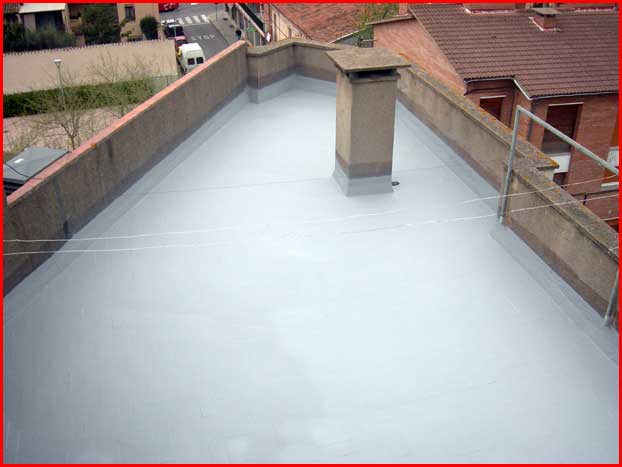
Liquid waterproofing membrane
Liquid Roofing
is the process of waterproofing a roof by the application of a specialist
liquid roof coating. It is suited to all types of roof, including flat,
pitched, and domed. Liquid roofing involves the application of a monolithic,
fully bonded, liquid based coating to a roof. The coating cures to form a
rubber-like elastomeric waterproof membrane, capable of stretching and
returning to its original shape without damage. Such coating systems are
usually reinforced with secondary materials such as glass-reinforced plastic to
provide additional tensile strength. The coatings can be applied over most
traditional roofing materials, including felt, asphalt, bitumen, and concrete.
The process of
liquid roofing provides a cost-effective method of making a new or existing
roof waterproof. It can deliver up to 25 years performance depending on the
coating system employed. It is estimated that liquid roofing is 70% less
expensive than overall roof replacement in refurbishment situations.
Bituminous waterproofing
Bituminous
waterproofing systems are designed to protect residential and commercial
buildings. Bitumen (asphalt or coal-tar pitch) is a mixed substance made up of
organic liquids that are highly sticky, viscous, and waterproof. These systems
are sometimes used to construct roofs, in the form of roofing felt or roll
roofing products.
Bituminous Coating Waterproofing Method
Bituminous coating is a type of coating used for
waterproofing and flexible protective coating. It is an excellent protective
coating and waterproofing agent, especially on surfaces such as concrete
foundations.
Bituminous membrane waterproofing is a popular method used
for low-sloped roofs due to their proven performance.
Polyurethane Waterproofing
Polyurethane is
made up of two components, base and reactor. Polyol acts as the base, while
isocyanide is the reactor component. The combination of both these in a
specific design ratio creates a liquid coating for waterproofing applications.
Polyurethane is a rather popular choice due to its ease of installation. Unlike
other waterproofing systems like sheet membranes and liquid applied membranes,
this polyurethane application requires comparatively less skill and
supervision. Application is fast and this type of treatment can be used for
post construction applications as well.
It is easy to install, provides seamless finish and have a long term durability and wear resistant. It is UV and weather resistant alkaline cleaners, battery acid and fuels.
Geosynthetics and systems made of geosynthetics(Geosystems in general)
are used for various applications in civil, environmental and other engineering
applications.
Geo-systems facilitate sustainable construction by reducing the use of
natural materials like aggregates & sands. For instance the thickness of
the aggregate layer in a typical cross section for road construction can be
reduced (by also keeping in view of the provisions in the code) so that less of
quarrying is required adding to sustainable construction. Similarly in river
training works and sea wall construction also the use of sand/aggregates for
creating protection structures or barriers could be eliminated to a major
extent by making use of dredged and reclaimed materials (locally available
slurry or any such by encasing them in the suitable Geo-systems or in tube forms
known as Geosynthetics containers or Geotextile tubes).
Here is trying to
outline some of the applications (only
some!) of Geo-synthetics systems for you all.
Flood control: Geo-systems for flood control
Flood control bags,
Geo-tubes and other stand alone systems or combination mechanisms.(Huge woven
Geo-bags for example)
Depending upon the specific
condition prevailing this need to be designed taking note of the historical
data available for flood occurrences previously such as HFL and other
engineering considerations.
Erosion Control: Erosion control mechanism with Geo-synthetics
Systems made of Geo-textiles(Woven
or non Woven)| Gabions|Grids and other products again independently or combined
together as per the specific purpose for which this needs to be designed.
For example river banks,
steep slopes on cuttings and beach side would require different considerations
while selecting the system. Geo-tubes would be suitable for beach nourishment
and prevention of erosion on the marine front. However the gabions may be more
suitable if the height is more because this could be constructed as a wall by
itself to protect the side slopes.
Embankment construction on
soft soil: PVD’s/Geo-grids and other
Geo-systems.
It could be formation for a
road or a railway line and in such a cases geo-grids and high strength woven
geo-textiles or other products needs to be used again as per a specific design.
In cases where the soil
bearing capacity is negligible there is also a need to do ground improvement in
the first place.
If it is a dredged and
reclaimed area then it calls for using the vertical drains (Pvd’s) to facilitate
the process of consolidation relatively easy to start constructing on a faster
basis.
Sub-grade strengthening:
Geo products can be made use of in
strengthening applications very effectively.
In all such applications
depending on the particular site specific data the geotechnical engineer and
the consultant in charge of the project need to take a call on the appropriate
geo-synthetic system that would bring in the desirable results.
Often Geotextiles, Geogrids
and even Geo-cells would be ideally suitable for these types of applications.
River training works and Sea wall construction:
Geobags|Geotubes|Gabions
are some of the systems used in this case.
There are soft solutions and hard solutions in these cases again. While mostly in river training Geobags or even Gabions could be utilized. Of course there are other new systems also being developed.
But when it comes to sea walls the concept is different. Obviously we are tackling a big wave force in these cases and also we need solutions which will sustain even the effect of Tsunami waves if such a situation were to occur. So seawalls are ideally made in combinations with large sized rocks/quarry stones which is used also along with appropriate Geo-systems.
These are some of the applications of Geo-systems. In fact the applications of Geo-synthetics in civil engineering being a vast topic only an attempt to touch the very basic aspect is made here. Please do not forget that, apart from facilitating sustainable construction, Geo-systems serve the precious purpose of protecting life and property from the vagaries of nature by being part of the control systems in various situations in coastal protection, river training, sea erosion control and flood control applications!
About Author:
Prakashan. B.V
Founder: bvprgj consultants
Independent Consultants For Sustainable Engineering Products and Services Promotion|Helping SME’s and Business Owners to Move Forward
We are independent consultants for sustainable engineering products and solutions promotion. Our work is based on the philosophy that whatever we do should be meaningful and adding value to not just the industry but to the society as well. As consultants for the promotion of geosynthetic systems, we have been instrumental in helping our clients procure and install the right geosystems aimed at protecting the precious lives and safeguarding the property. Apart from that we support the Small and medium manufactures(SME) of engineering products and other business owners to get maximum leverage for their products and services by making use of the cost effective methods to get more end users.
The advent of innovative designs keeps prompting formwork manufacturers to come up with new and custom solutions to meet the needs of abstract projects. Contemporary building system is dominated by complex geometries and ever-higher buildings, and the success of these projects depends largely on efficiency in the construction process.
Discussed below are few of the innovative
formwork technology adopted across the globe,
Modular
Formwork Systems are generally easy to assemble and much faster than
conventional Formwork, saving time, allowing you to pour sooner.
In addition, with the option to hire, Modular Formwork Systems save contractors by reducing the costs associated with conventional purchases. This eliminates the need to recover purchase costs by reusing or reselling materials once the job is complete.
When
choosing to either buy or hire formwork you should look for a supplier who
provides:
Advice
on the latest innovations and formwork solutions within the formwork industry,
Safety and guidance through well
planned design & support,
Quantity take off’s to accurately
provide material costs pre construction, and
Re assurance knowing that the
equipment is serviced and tested and therefore quality assured.
There are many advantages to using a Modular Formwork System that can assist you in your scope of works. Adding value to your project by providing innovative time saving solutions but never at the expense of safety and quality.
The advantages of this are;
Fast assembly when compared to conventional formwork,
Less complications and “surprises” on site,
Hire costs were significantly less than the upfront purchases for conventional formwork components,
Re assurance knowing that the hired equipment had been serviced and tested prior to use,
Share of responsibilities between Contractor and supplier.
Modular formwork systems are designed
with standardized panels and component items to reduce or limit the need for
cutting material on site. This speeds up
the overall process and therefore requires less labour on site. They are also
interchangeable with conventional methods.
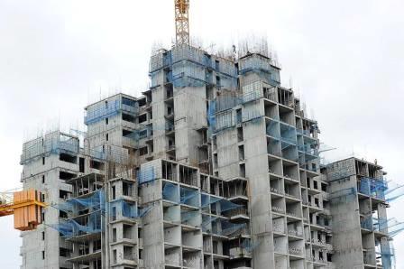
FORM WORK MANAGEMENT BASED ON
UBIQUITOUS COMPUTING FOR HIGH-RISE BUILDING CONSTRUCTION
The recent
development of ubiquitous computing has resulted in an improvement of
management performance through real-time monitoring and control. Especially, in
high-rise building construction with reinforced concrete structures, form work
requires effective management systems to reduce the duration and cost of
structural frame work and subsequent activities. Recently, a concrete curing
management system by adapting a ubiquitous computing environment has been
developed as a method for effective quality management.
The
constitution of the existing wireless temperature monitoring system is in Korea. The system transmits the
temperature data measured from the sensors wirelessly in real-time into the
personal computer in the site office, and estimates the maturity and concrete
strength. The data are also stored in the computer server, and information is
shared with related experts for technical support.
FIBERGLASS SHUTTERING
Fiberglass
Reinforced Plywood System is the key to
that perfectly cast roof with the smoothest finish that requires no
plastering.This fiberglass shuttering building systems represent a revolution
in the area of shuttering because of their lightness, simplicity, durability,
solidity, resistance to temperature changes and their price competitiveness.
One of the major advantages with these systems is that they offer simplification
of shuttering with the same mechanical properties of other systems.
Advantages
Smoothest finish among existing concrete formwork and shuttering systems
Unmatched building quality and durability
Lower cost, no plastering required & faster project delivery
Easy customization and repairability
High re-usability
TUNNEL FORMWORK
Tunnel form is a
formwork system that allows the contractor to cast walls and slabs in one
operation on a daily cycle. It combines the speed, quality and accuracy with
the flexibility and economy of in-situ construction. Construction durations are
reduced significantly by this rapid system when compared to conventional
methods. Tunnel Form System brings speed, quality and accuracy to concrete
construction and provides big savings in finishing and M&E works. Hi-tech
technologies for steel formwork production make tunnel forms strong &
durable. The system creates efficient load-bearing structures which are known
as the most earthquake resistant structures.
The result is a
cellular reinforced structure, the surfaces of which are sufficiently high
quality to require only minimal finishing for direct decoration, while the end
walls and facades are easily completed with thermally insulated units that can
be clad as required. The system creates an efficient load-bearing structure for
use in a wide variety of applications. It is particularly effective in projects
suited to repetitive cellular construction such as residential blocks, hotels,
student accommodation, barracks and prisons.
Architectural concrete has developed into one of the
most important means of design in modern architecture. No other building
material can be used and processed in such a versatile manner. Therefore,
architectural concrete is used for almost all construction tasks.
Through the design capabilities of the fresh
concrete, virtually any shape and quality can be economically realised with the
help of appropriate formwork systems and formlining.
The creation of architectural concrete as a design
element is influenced by the following:
Formlining and formwork system.
Concrete mix, including type of cement
and aggregates.
Added pigments.
Selection of a suitable release agent.
Subsequent surface treatment, such as
washing, sanding, polishing and sandblasting.
Hydrophobizing impregnation, colour
varnishing and coatings.
The development of the building material
concrete with new concrete types such as high-strength, lightly-compacted and
self-compacting concretes as well as fibre-reinforced concretes (steel and textile
fibres) opens up further areas of application.
SEMI-SYSTEM FORMWORK
This
is a more advanced formwork type than the modern conventional type as there are
prefabricated formwork items. For example there are prefabricated formworks for
slab panels and supports and other structural parts.
FABRIC
FORMWORK
Fabric formwork is a building technology that
involves the use of structural membranes as the main facing material for
concrete moulds. Unlike traditional formwork, the material is highly flexible
and can deflect under the pressure of fresh concrete. The resulting forms
exhibit curvature as well as excellent surface finishes that are generally not
associated with concrete structures.
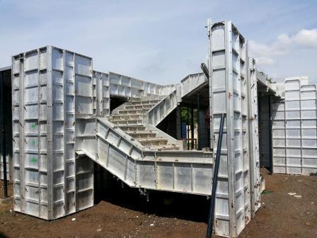
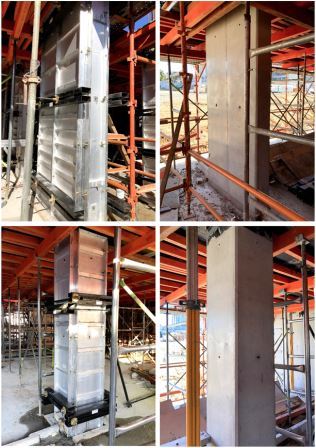
The
Perfect Aluminium Panel System is a long life and easy maintenance formwork
system which guarantees 200 times monolithic pouring. A special extruded
profile made from a robust aluminum alloy provides the Perfect Aluminium Panel
with its high level of rigidity and versatility. Combined with superior quality
15 mm thick formwork panel, birch plywood and plastic overlay the Perfect
Aluminium Panel System can absorb high levels of concrete pressure. The Perfect
Aluminium Panel System with its systematic modular design and corrosion
resistance offers high assembly efficiency and good construction quality making
it an ideal formwork for the modern construction industry.
PERFECT ALUMINIUM PANEL (PAP)
SYSTEM ADVANTAGES
Systematic Modular Design.
Light Weight Formwork – Panels weigh:22 to 30 Kg/m2.
Multiple family sizes for columns and wall panels i.e.: common height families (cm) : 60, 90, 120, 240 ; common width families (cm) : 15, 30, 45, 60, 75.
Permissible fresh concrete pressure 60kN/m2, complying with international Standards.
Finish: mill finish – special alum alloy.
Corrosion Resistant.
Crane Independent.
Offers Long Life and Easy maintenance.
Adopts plywood panel with plastic overlay.
Sheathing options available are plywood or plastic.
Utilises state of the art manufacturing technology.
External working platform is provided.
Perfect Accessory System for use with minimal tools.
Offers standard health and safety protection.
All system components are manufactured in RS Group premises.
This article introduces the methodology for durability design of marine Concrete infrastructures for a “major” maintenance free life of 120 years. A change of design approach is recommended, from the conventional “prescriptive approach” practised by current design standards to “performance-based approach” which considers the actual ageing process through probabilistic treatment. Corrosion of steel reinforcement is the most critical process and subjected to performance-based design. The target design life and durability limit states are attributed to concrete elements according to their structural importance and ease of maintenance. The thickness and quality of concrete covers can be designed using a full probabilistic approach for a target probability of corrosion initiation for a life of 120 years. This article is based on the authors experience in providing durability design for infrastructures.
1 Motivation
The demand
for human development worldwide continues to grow, and much of this development is occurring in the marine
areas because of the great advantages of coastal localities in terms of trade
and transport opportunities, areas suitable for human habitation, recreation and accessibility. The current global population is
approximately 7.3 billion, of which approximately 44% is estimated to live within 150 km of the sea [1].
India has close to 7500 km of coast
line and major states
of the country sharing this coast
are highlighted in Fig. 1. An example
demonstrating the importance of coastal infrastructure is the Sagarmala programme
initiated by the Government of India (GOI). The mission
of this programme is to invest close to Rs. 4 lakh crores (Rs. 4
trillion) [2] in modernising marine infrastructure. Such huge investment demands
that the built facility be maintenance free and attain its intended service-life, since the return
on this investment is justified by the
service-life attained and the life cycle cost.
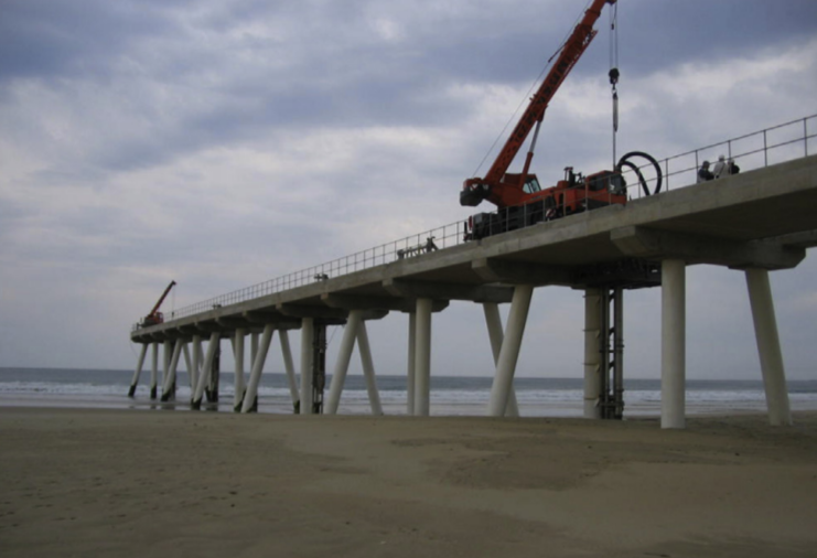
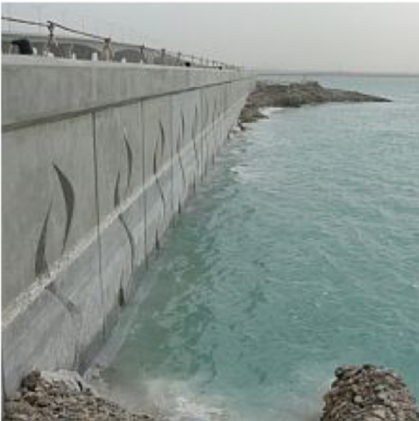
Reinforced
Concrete (RC) is widely used in the marine environment, and in its various forms permits the construction of coastal
facilities, including docks and harbours, quays, jetties, wharves, seawalls, pipelines, tunnels, and so on, which in turn facilitate on-shore and near-shore developments. It is also
a popular choice for infrastructure of coastal cities, such as bridges, residential structures, warehouses and administrative institutions. Concrete will continue to be the construction material
of choice for use in marine environments, as well as in a range of other
demanding environments, into the foreseeable future. At this stage,
there is simply
no other viable alternative [3].
Chloride induced
corrosion of reinforcement steel is the leading cause of deterioration of reinforced concrete structures in marine environment [4], reducing the service-life of such infrastructures. The annual cost
of corrosion in India is 3% to 4% of the Gross
Domestic Product (GDP) [5]. This loss can be avoided
by adopting “performance based durability design”
[6, 7] with a specific target
service-life which serves
to be economically most profitable and adds value
to the project.
Figure 1: Coastal states in India
2 Concrete Durability
Concrete durability problems arise from the aggressiveness of the environment to which the structure is exposed. Different
exposure conditions in the marine environment is shown in Fig. 2. Such exposure
promotes chloride induced
corrosion of reinforcement steel.
Figure 2: Exposure conditions in the marine environment [8]
The main reasons for such durability problems
are the interconnected porous nature of the hydrated cement paste.
In
the construction industry, durability
is expected to be achieved through
strength. But there is no simple or unique relationship between strength and
any of the durability parameters [9, 10].
For
example, a given grade of concrete made with different binders types say pure Ordinary
Portland Cement (OPC) or OPC blended with Supplementary Cementitious Material
(SCM) will have different durability
property (database [11]), but same strength. The key to concrete durability is the achievement of a “designed concrete pore structure”. The unique way towards this goal is by specifying the concrete accurately for
its intended purpose. The specification should address different aspects such as
intended service-life, quantifiable description regarding serviceability requirement and failure,
acceptable level of risk and possible extent
of maintenance.
2.1 Conventional durability design
Conventionally, the durability design
of a concrete structure for a target
working life is achieved
using a “prescriptive (deemed-to-satisfy) approach”. The prescriptive approach,
based on acquired
experiences and empirical data, provides the requirements for material
composition and structural details for given environmental actions and target
working lives. This approach is followed by most
design codes in use (IS 456:2000 [12],
IS 4651:2014-4 [13],
IRC 112:2011 [14], IRS
CBC:1997 [15]). The provisions include limits
of
Minimum cement content,
Maximum water cement (w/c) ratio
Minimum grade of concrete
Nominal concrete cover
However, the fulfillment of a particular service-life (say 120 years), if all of these prescription are satisfied, cannot be quantified using this approach.
In other word, if all requirements are satisfied, what will be the
achieved service-life? Further this
approach neither quantifies what constitutes the end of service-life. To provide
solution to such a question, there is an increasing
demand to incorporate more advanced concepts related to concrete durability, due the need
to better foresee and prevent distresses, in particular the corrosion of the reinforcement.
3 Performance based durability design
The
corrosion process in concrete is highly complex with various physical-chemical
interactions among saline
solutions, solid phases
of concrete and moisture. The complicated nature
of the process leads
to significant uncertainty when modelling corrosion [16]. In addition
there is significant uncertainty associated with
some of the parameters which
dictate corrosion initiation, such as the time
dependent diffusion coefficient, the critical chloride
content and the provided
concrete cover [6, 7]. The presence of such engineering uncertainty necessitates the adoption of “performance-based
approach” for design. The performance-based approach involves modelling the
real ageing process
of structural materials under environmental actions
and employs mathematical models to evaluate the
required properties and structural dimensions for expected design lives
through probabilistic treatments. These methods allow
the uncertainty associated with all levels of corrosion process
to be incorporated into
the analysis, leading
to a robust and informed design. The performance-based approach is an ‘engineered approach’ to durability design.
Considering structural design of durability for corrosion processes, the design factors
are listed in Table 1 as
concrete cover quality
(diffusivity), concrete cover thickness,
and crack control criteria. The concrete cover quality
and thickness are designed through
the durability models with
the target service
lives and appropriate DLS adopted. For the performance design procedure, the concrete surface
is supposed to be exposed directly
to aggressive agents (Cl−). The model-based design follows
a reliability analysis
format with a target probability of failure, PT[6].
Table 1: Durability
Requirements
Material
Structural
w/c ratio
cement
type cement content
cover quality
cover thickness crack control
3.1 Design Life and Durability Limit State
The asset
owner desires a working life
of 120 years
for a particular port concrete facility. Aiming for this target, the durability design should first decide the working lives for each elements on the basis of their structural
importance and technical feasibility. The
basis being that the principal elements have
the same working life as the whole project (120 years), whereas the
secondary or replaceable elements can be shorter.
For these elements the maintenance
and replacement schemes should be specified in the design phase.
Durability
Limit States (DLS) are needed for quantitative durability design using the performance-based approach. These are the minimum
acceptable performance levels for different durability processes. For corrosion process, two DLS can be defined: (a) corrosion initiation state, and (b) corrosion to an
acceptable extent. As an example IRS CBC:1997 [15] specifies that under external loads the permitted
design crack width can be 0.1 mm or 0.2 mm depending
on exposure condition, for Reinforced Concrete (RC) elements. Whereas no
cracking is permitted for Prestressed Concrete (PC) components. In a marine port project,
PC elements, principal RC elements, and RC elements with high maintenance difficulty should adopt
DLS (a), while secondary RC elements
may adopt DLS (b). The stages
in life of a corroding concrete element is shown in Fig. 3 [6] for visualising various DLS.
Figure 3: Schematic description of phases in corroding concrete
3.2 Corrosion deterioration model
The design
model for chloride-induced corrosion is adapted
from the analytical model of diffusion. With the DLS specified as the
corrosion initiation state (a), the design equation can be written as [6],
G = Cth− C(Cs,xd,Dc,TSL) (1)
The objective being to
obtain cover thickness (xd) and specifications of the concrete such as the chloride
diffusion coefficient of concrete (Dc) for
the specified design
life (TSL=
120 years) subject to
P (G < 0) ≤ PT(2)
C( ) is the chloride
concentration function in concrete. This model has four governing parameters
Threshold
chloride concentration (Cth)
Concrete
surface chloride concentration (Cs)
Chloride
diffusion coefficient of concrete (Dc)
Concrete cover thickness (xd)
3.3 Preliminary Design
These
four parameters have significant
dispersion for a given exposure condition, and their statistical nature
must be taken into
account to guarantee a large enough
safety margin for the
durability design. As mentioned earlier, the target probability of failure is
fixed as PTfor the design at this stage. Towards this aim, the design is performed by a full probabilistic scheme using directly the statistical properties of the parameters.
The statistical properties of model
parameters are analysed
on the basis of the long-term
in-place structural investigations and exposure tests
conducted in the
vicinity of the
proposed project in the past or based on literature. It is advised
to identify these
parameters and must be
included in the feasibility investigation for the project. The
investigation comprises of environmental data extracted
from site investigation for atmospheric temperature, humidity, and air-borne chloride content and wind speed. Further, the evaluation of
chloride/carbonation profiles of structures in the vicinity
of the proposed project or similar projects
elsewhere must be incorporated.
This investigation helps
to statistically characterise the diffusive property
of concrete and evaluate the distribution of surface chloride
concentration. Since the concrete cover
is the only structural parameter in the design
equation, correct specification of concrete cover
thickness is the central issue
for durability design.
The statistical properties of concrete cover
thickness are important for correct estimation of reliability with
respect to the
design equation, and are related closely
to the construction methods and practice. Statistical analysis based on the
data of achieved
cover thickness of similar
concrete infrastructures must
be investigated or
tolerance prescribed by the codes may be used.
3.4 Design assisted by testing
Based
on the preliminary design, the required construction material and
specifications for executing the design can be
used as design basis for the project. However,
every project is unique and precise
characteristic of the design are quantified by testing the material used at
project site.
During the construction, the properties of structural concretes should be tested in on-site
laboratory. In parallel, the constructed concrete elements, prefabricated or cast-in-place, are
inspected for the
achieved quality, and particularly
for the thickness of concrete over. These
data provide the information on the realistic
construction quality of concrete elements,
thus help to update the statistical properties of parameters in the
durability assessment models. The measurements
of concrete cover thickness for the
cast-in-place concrete elements are done either through, ground penetrating radar, electromagnetic test, ultrasonic and radiography.
The in-situ
data of chloride diffusion coefficient of structural concretes
are to be collected from the on-site laboratories for different concrete elements. The
chloride diffusion coefficients are measured on structural concretes under standard conditions by rapid
migration method [17]. The concrete surface
chlorides are tested
as per [18] and airbourne chlorides is obtained form [19]. The critical
threshold chloride concentration is evaluated by the accelerated chloride threshold testing [20]. Additions of admixtures such as ground granulated
blast furnace slag, fly ash, silica fume
and metakaolin alter
the properties of ordinary portland
cement concrete. Test- ing of such concrete
is therefore crucial
to study its chloride ingress
property and statistically characterise it to apply in the performance-based design.
This updated
data source, form the essential basis for predicting the durability performance of concrete elements during
its service-life.
3.5 Monitoring and Maintenance Planning
The maintenance planning is to establish the techniques and intervention periods
of maintenance, on the basis
of the durability states of the concrete elements. The strategies of maintenance planning
is to be preventive/proactive, which
refers to the intervention at early stage of
deterioration, normally at low maintenance costs.
During the service-life, the deterioration processes will be
monitored via periodical inspection and sensors. The maintenance actions
are to be taken at early stage of deterioration for elements with the help of these inspections and monitoring. Since concrete elements
are designed in such a way that the probability of corrosion
initiation (PT)
will only be exceeded
after 120 years,
technically all elements
can be exempted from maintenance during the service-life. However, given
the uncertainty associated with the concrete construction, e.g. early-age cracking,
unintended lower concrete cover, accidental use of saline
water for concrete
mixing and/or curing
and the unexpected environmental actions during service-life, e.g. the global warming
and long-term change
of ambience, a basic maintenance planning is necessary for concrete elements. Through monitoring of as-built concrete components it is possible
to establish the service-life of the casted components in real-time.
The basic
maintenance planning considers mainly two aspects: the durability performance monitoring, and maintenance of the elements. Monitoring involves: potential mapping, resistiv- ity mapping, embedded anode sensors, cover thickness measurement, air
permeability, chloride profile, etc. It is also beneficial to cast test concrete elements
near the actual
structures so that monitoring can be done on them rather
than the actual
components. The maintenance scheme consists of performing the surface chloride
extraction by electrochemical method
or a cathodic protection system can be installed to protect the steel bars against the unexpected durability failure. It should be noted
that this basic
maintenance scheme is to interact
with the durability inspection/monitoring data
and the real-time durability assessment during
the service-life. A predictive maintenance scheme is setup for the same.
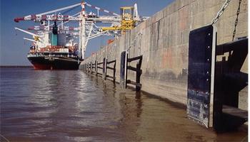
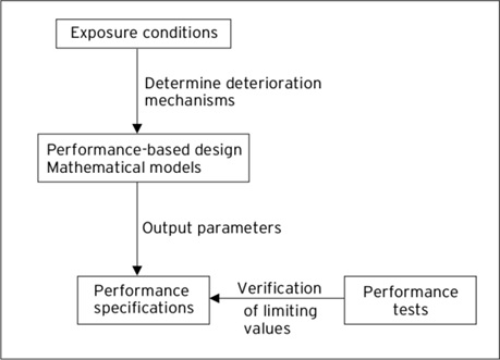
3.6 Summary
In
essence the performance-based approaches is fundamentally a measurement and
verification design
procedure. Fig. 4 [6] provides a schematic of this performance-based approach.
Figure 4: Schematic representation of the performance-based approach
4 Case study
As requirement for a new concrete harbour,
a service life of 120 years is specified for a caisson
quay wall. The part of the caisson
facing the tidal zone is the most prone to corrosion
initiation.
4.1 Conventional strategy
As per
IS 456:2000 [12], the exposure condition can be considered to be “Extreme”. The
“durability design” for Extreme exposure according to current prescriptive
provisions of IS 456:2000 [12] are:
Minimum nominal cover : 75 mm
Minimum cement content : 360 kg/m3
Maximum cement content : 450 kg/m3
Max w/c ratio : 0.4
Aggregates : 20 mm nominal maximum aggregate size complying IS 383:2016 [21]
Min concrete grade : M40
As highlighted previously, by satisfying all the prescriptive requirements the following important aspects remain unanswered:
Actual achieved service-life
How to consider Global Warming effect
Recommendation on type of cement
4.2 Performance based strategy
In this section two tasks will be
undertaken:
The prescriptive durability design will be benchmarked using the performance based
design to calculate the actual achieved service
life.
Actual performance calculation will be done to design the caisson for 120 years.
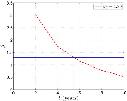
The
target probability of failure is PT= 0.10, which corresponds to a target reliability indexβT= 1.3. The governing parameters of the design are
probabilistically quantified as follows:
Chloride load: A chloride surface concentration is a Gaussian parameter having mean 5.5
% weight of cement with 1.3 % weight of cement as standard deviation [22].
Critical chloride: A critical chloride concentration at reinforcement level for corrosion initiation is 0.6 % weight of cement and 0.15 % weight of cement as standard deviation. This is a Beta distributed variable with limits of 0.2 and 2 % weight of cement [23].
Chloride diffusion: For comparison two types of concretes varying only in cement types viz. OPC and OPC+Slag SCM, but same w/c=0.4. The chloride diffusion values are sourced from database [11]
Global warming: At present the average temperature at the site is 27.83 ◦C with a standard deviation of 2.7 ◦C. Future anthropogenic emissions of greenhouse gases and aerosol particles would cause climate change and temperature rise. In the IPCC Fifth Assessment Report released in 2014 [24], some climate change scenarios were simulated and referred to “Representative Concentration Pathways” (RCPs). In the present project a medium stabilisation scenarios (RCP 4.5) is considered.
Clear cover: The concrete cover is 75 mm with standard deviation of 6 mm, which implies execution requirements targeted. This is a Beta distributed variable [23]. Based of the design a revised cover is adopted.
4.2.1 Results
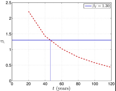
Fig. 5 shows reliability
plot and service-life achieved by using
OPC cement and using the conventional approach. The achieved service-life is 5.48 years.
This is far from achieving
Figure 5: Benchmark of conventional approach with OPC concrete and 75 mm cover
even a life of 10 years let alone achieve
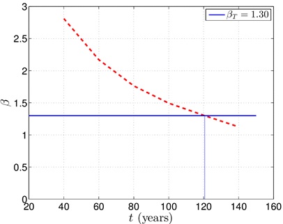
a life of 120 years. Fig. 6 shows reliability plot and service-life achieved by using OPC+SCM cement and using the
conventional approach. This shows that the achieved
life is 46.4 years which is more than the previous analysis
but still far from
achieving a life of 120 years. This highlights the importance of the performance based “design”. Fig.
7 shows reliability plot and service-life achieved by using OPC+SCM cement and using the performance based approach, the service-life achieved is 120.58
years.
Figure 6: Benchmark of conventional approach with OPC+SCM concrete and 75 mm cover Figure 7: Performance design for 120 years service-life
The
performance approach offers following advantages:
Quantification of achieved service-life for any design
Design modification under non-compliance of actual service-life
Allows choosing of concrete types
Incorporates climate change which manifest over the long service-life
Allows practically for the non-maintenance of the infrastructure
Design option of using stainless steel, lower w/c concretes and other SCMs is also possible through which further reduction of concrete cover is possible
Decisions can be based on life-cycle cost assessment
5 Inclusion in Tender document
In
the present scenario, asset owners of coastal ports specify the conventional
prescriptive requirements as per code in the design basis report. However, they wish to know how much
really is the achieved service-life and what can be done to have a
“major” maintenance free life. It is necessary that the change should begin at
tendering stage of the project.
The tender
document should mandate
the requirement to study the durability factors
and incorporate in the feasibility
exercise, to evaluate all the environmental parameters responsible for
degradation, including review of previous statistics for similar projects
elsewhere. This will be the design
basis for the preliminary performance-based design. The asset owner must emphasise on specific durability limit state as per their
requirement and mention
the expected service-life
and target probability of failure. Testing of
in-situ components along with the magnitude of tests to be performed are necessary part of the design basis. The asset
owner must press for the requirement of probabilistic durability design in the tender document
with a design report.
And finally long term monitoring and updating of actual service-life must be
included as part of the contract.
6 Conclusions
There is massive capital
investment on coastal infrastructure in our country. To safeguard these investments and avoid costly repairs and renovation due to
premature deterioration of RC structures, it is prudent
to verify the properties of concrete cover (its penetrability and thickness).
This technical article
recommends the change
of approach to the asset
owners/concrete industry from traditional prescriptive approach to the performance-based specifications. It highlights important steps involved in the durability design of
concrete components with a case study. It
is recommended to bring about a change of approach from the tendering stage
itself. The applicability of this technology is universal, both for new infrastructures
[6, 7] as well as for repairing the
existing assets [25].
References
UN Atlas. 44 percent of us live in coastal areas. http://coastalchallenges.wordpress.com, 2010. Retrieved January, 2019.
K Scrivener. Options for the future of cement. The Indian Concrete Journal, 88(7):11–21, 2014.
A. A. Almusallam, A. S. Al-Gahtani, A. R. Aziz, F. H. Dakhil, and Rasheeduzzafar. Effect of reinforcement corrosion on flexural behavior of concrete slabs. ASCE Journal of Materials in Civil Engineering, 8(3):123–127, 1996.
N. G. Thompson, M. Yunovich, and D. Dunmire. Cost of corrosion and corrosion mainte- nance strategies. Corrosion Reviews, 25:247–261, 2007.
S. A. Faroz. Performance Based Durability Design of Bridges for 120 Years. Indian Society of Structural Engineers (ISSE) Journal, 20(3):10–15, 2018.
S. A. Faroz. Durability Design Methodology of Metro Rail Bridges for 120 Years. Metro Rail News, 2:26–31, 2018.
BS. BS 6349-1 Maritime Structures Part 1: Code of Practice for General Criteria. British Standards, London, UK, 2000.
A. Neville. Consideration of durability of concrete structures: Past, present and future.
Materials and Structures, 34:114–118, 2001.
R. N. Swamy. Sustainable concrete for the 21st century concept of strength through durability. http://www.jsce.or.jp. Last accessed: January, 2019.
DARTS. Durable and Reliable Tunnel Structures: Data. Technical report, European Commission, Growths 2000, 2004.
BIS. IS 456 Indian Standard for Plain and Reinforced Concrete – Code of Practice. Bureau of Indian Standards, New Delhi, India, 2000.
BIS. IS 4651-4 Indian standard for Code of practice for planning and design of ports and harbour: Part 4 General design consideration. Bureau of Indian Standards, New Delhi, India, 2014.
IRC. IRC 112 Code of Practice for Concrete Road Bridges. Indian Roads Congress, India, 2011.
IRS. IRC CBC Code of practice for Plain, Reinforced & Prestressed Concrete for General Bridge Construction. Research Designs and Standards Organisation, Lucknow, India, 1997.
S. A. Faroz. Assessment and Prognosis of Corroding Reinforced Concrete Structures through Bayesian Inference. PhD thesis, Indian Institute of Technology Bombay, Mumbai, India, 2017.
NT. NT Build 492 Concrete, Mortar and Cement Based Repair Materials: Chloride Mi- gration Coefficient from Non-Steady-State Migration Experiments. Nordtest Method, 1999.
ASTM. ASTM G140 – 02 Standard Test Method for Determining Atmospheric Chloride Deposition Rate by Wet Candle Method. ASTM International, USA, 2014.
D. Trejo and R. Pillai. Accelerated Chloride Threshold Testing: Part I – ASTM A 615 and A 706 Reinforcement. ACI Materials Journal, 100(6):519–527, 2003.
BIS. IS 383 : 2016 Coarse and Fine Aggregates for Concrete – Specifications. Bureau of Indian Standards, New Delhi, India, 2016.
O.E. Gjorv. Durability design and quality assurance of major concrete infrastructure. Advances in Concrete Construction, 1(1):45–63, 2013.
fib. Model Code for Service Life Design. Federation Internationale des B´etons, Lausanne, Switzerland, 2006.
IPCC. Fifth assessment report of the intergovernmental panel in climate change. Cam- bridge University Press, London, 2014.
Author
Dr. Sharvil Alex Faroz, PhD (IIT Bombay),
CEO, Infrastructure Risk Management (IRM)
With the massive developments in the construction and construction material industry in India, demand for building materials has witnessed an upsurge. In addition to building materials like timber and steel, the demand for sustainable and environment-friendly products such as aluminium formwork and used materials has also risen, according to reports. There is a need to meet the growing demands for building and industrial material manufacturers, suppliers, and retailers. Formwork system is one of those systems which inhibits economical structure with less time needed to complete a project.
The determining factor in the growth of the formwork market is the strong demand for the construction sector. The industry is growing at a very fast pace and it is estimated that the current cement production will become double in the near future. According to researchcosmos.com/reports, overall formwork market size is estimated to reach around USD 6.12 billion by 2024 from 5.21 Billion in 2017 registering a healthy CAGR. This growth is taking place because construction companies are paying high attention to labor and severe time-saving methodologies. Spending or investing in infrastructure and real estate developments are one of the most potential growth opportunities towards the formwork market.
MEETING THE CHALLENGE OF THE MARKET
With the current thrust of the government on construction and infrastructural development, the building material industry is booming opportunities. However, time and cost constraints remain a challenge. Another nagging concern is the requirement of trained professionals in the field. Increasing demand in the wake of ongoing and future projects, formwork manufacturers are keeping pace with the construction industry.
Further,
project requirements have changed at last, wherein they have started accepting
innovated products, which reduce human effort providing better quality.
Traditionally, timber and plywood are used for formwork fabrication for the construction of concrete structures. However, it needs many skilled and unskilled workers besides being very time-consuming. In today’s competitive market, speed and efficiency are of primary importance. Hence, more demand in the market, for Aluminium formwork, as many builders prefer this system to the conventional ones, for its speed, high repetition, cost, avoidance of plastering and 25% regeneration of scrap value from the invested amount.
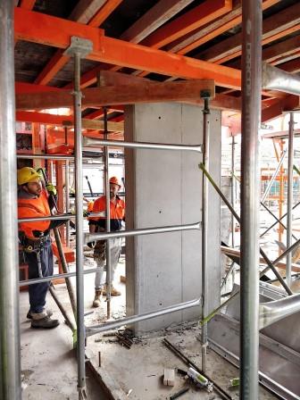
THE INNOVATION IN FORMWORK VIA IHITA
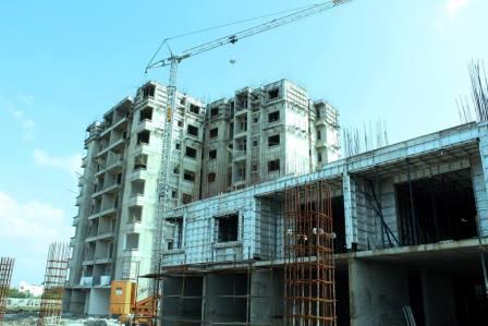
Ihita aluminium formwork system offers competitive costing with improved quality, at an international standard. Using this system formwork, the overhead cost is lesser, thus posing a great advantage for builders. On a long-term, 2/3rd construction time is reduced. With a guaranteed and proven minimum of 200 cycle times Monolithic Casting Aluminium Panel Formwork reduces break-even time and provides a superior wall finish, thereby saving a lot of finishing time and plastering material.
Ihita engineering Services Pvt Ltd is an esteemed global firm, based in Chennai, India, specializing in Aluminium Formwork Design, Manufacturing and Installation. Standing As the fastest growing aluminium formwork supplier, Ihita has undergone several projects in India, South America, Australia, France, Singapore and Sri Lanka, including prestigious clients like NCC Ltd, Godrej Properties Ltd, Vascon engineers Ltd, Samridhi Realty, Aliens Developers, SPCL, Casagrande Group, Panchsheel Buildtech Pvt. Ltd.
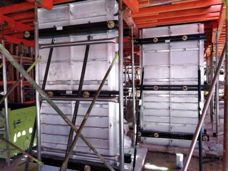
Sustained in
the market for almost a decade, Ihita system comprises of Column Box Formwork,
Lift and Core Wall Formwork System, Staircase Formwork and Complete System
Formwork. The Assembly of panels are designed for reduced labour time, easy
installation and no requirements for trained professionals.
PRODUCTION EFFICIENCY IN IHITA FACTORY
Ihita has a
large production facility for Aluminium Formworks System that extends more than
25000 sq.ft. of area. Ihita’sfactory at Madurai, has a capacity of 30,000sqm
per month, and the vendor factories at Vijayawada and Bangalore has that of
20,000 sqm per month. Put together, this sums up to 50,000 sqm capacity per
month.
To assure the
quality of our products, the raw materials are tested in a third-party
laboratory accredited by NABL (National Accreditation Board for Testing and
Calibration Laboratories). Each material is checked by Q/C (Quality Checker)
team, before its dispatch.
Ihita is
equipped with imported quality machines for increasing quality and production
speed.
QUALITY POST SALES SERVICE:
Ihita
coordinates and supports client engineers, in terms of site training, so as to
obtain a satisfactory project. Value-added services are provided at the sites –
Ihita provides site engineer and supervisor at no cost, for 2 complete cycles.
Apart from the
quantity required, 15% of accessories are supplied. Further, Ihita is capable
and flexible to accommodate any changes in its products and also incorporate
any changes in the structure, post supply.
It is not just
the price which matters today but a combination of quality, timely-delivery,
consistently performing products, and most importantly, a complementing product
for an overall project. With ingenious Design team, experienced and
enthusiastic site Engineers and site supervisors, Ihita Aluminium Formworks is
now on the path of growth, emerging globally in the Building Materials market.
Thus, they are highly competent to cater to the demand of clients in the global
market.
The global formwork market size is expected to reach USD 6.06 billion by 2024. The growth is attributed to rapidly expanding residential and commercial construction sector due to new construction activities and renovation of old sites across the globe. Demand for residential spaces due to rising population will also present potential growth opportunities for the global market. Timber and plywood are the key raw materials used in manufacturing formworks. However, aluminum formworks are increasingly gaining popularity as they are light weight and have low density. Aluminum formworks have longer lifespan compared to their counterparts made of timber and plywood and therefore are more economical as well. Over the years to come, the market is expected to derive significant growth from aluminum formworks.
Construction companies are growing at a rapid rate where overall formwork market size is estimated to reach around USD 6.12 billion by 2024 from 5.21 Billion in 2017 registering a healthy CAGR. This growth is taking place because construction companies are paying high attention to labor and severe time-saving methodologies.
The determining
factor in the growth of the formwork market is the strong demand of the
construction sector. The industry is growing at a very fast pace and it is
estimated that the current cement production will become double in the near
future. In recent years, concrete technology has grown by leaps and bounds.
Advances in concrete technology have led to many innovations and emerging
trends as a result of construction speed and durability. New concrete
variations such as high-performance concrete, concrete with large ashes,
concrete powder reactive with superplasticizer even changed the perception of
the design, while posing new challenges in the field of formwork.
Formwork makers are situating their R&D towards turning out on account of item developments keeping the interesting working states of India. Peri, another worldwide market pioneer in the area, had prior in the year propelled Peri Liwa, a lightweight kind of board formwork, which can be utilized wherever there are just constrained crane limits accessible or where all the work must be done physically. Solid development of modules is normally utilized as a part of private lodging, where a similar design must be imitated in extensive numbers. This kind of formwork systems could assume a key part in India which is ready to enter a period of gigantic advancement of moderate lodging ventures.
In the development
business, diverse sorts of cement formwork are utilized. Generally, concrete
formwork is being utilized. Numerous sorts of formwork are accessible for any
building venture. In light of sort, the formwork market is delegated designed
formwork system, conventional timber formwork, re-usable plastic formwork, stay
set up auxiliary formwork systems, lasting protected formwork, and adaptable
formwork.
Why Formwork:
Acute shortage of
labour is amongst the key factors that have been driving forward the demand for
formwork and scaffolding systems. Labour shortage has added to the pressure on
contractors, who are already grappling with issues of construction costs being
on the rise. In this day and age of lean construction methods, featuring
tightened purses, semi-automated and automated formwork systems have come as a
boon.The Formwork should have sufficient strength to carry a dead load and live
load coming on it during casting operation and after that till concrete gets
hard and gain some percentage of design strength. Therefore choosing the best
one is almost a necessity for a successful system. Discussed below are some of
the popular formwork system available.
To fulfil the housing and infrastructure requirements of increasing population, in last few decades Indian construction industry has grown in large amount. With the introduction of multinational companies in Indian construction sector, accuracy and speed of work has increased. Now-a-days to cope up with the demand is becoming crucial. Conventional construction methods are economical but they are unable to give required quality work and speed. Hence, in today’s date there is a need to think on latest construction technology. Formwork is an important part of construction which takes almost 30-35% of total cost of construction. The various new technologies of formwork systems are introduced which helps to increase the overall economy, high quality construction and speed of construction. In this paper, analysis of new formwork technology implemented on site is done and it is proven that how it is more useful than the previous method of formwork technology.
Different types of
Formwork System
Traditional timber formwork: The formwork is built on site out of timber and plywood or moisture-resistant particleboard. It is easy to produce but time-consuming for larger structures, and the plywood facing has a relatively short lifespan. It is still used extensively where the labour costs are lower than the costs for procuring reusable formwork. It is also the most flexible type of formwork, so even where other systems are in use, complicated sections may use it.
Engineered Formwork System: This formwork is built out of prefabricated modules with a metal frame (usually steel or aluminium) and covered on the application (concrete) side with material having the wanted surface structure (steel, aluminum, timber, etc.). The two major advantages of formwork systems, compared to traditional timber formwork, are speed of construction (modular systems pin, clip, or screw together quickly) and lower life-cycle costs (barring major force, the frame is almost indestructible, while the covering if made of wood; may have to be replaced after a few – or a few dozen – uses, but if the covering is made with steel or aluminium the form can achieve up to two thousand uses depending on care and the applications).
Re-usable plastic formwork: These interlocking and modular systems are used to build widely variable, but relatively simple, concrete structures. The panels are lightweight and very robust. They are especially suited for similar structure projects and low-cost, mass housing schemes. To get an added layer of protection against destructive weather, galvanized roofs will help by eliminating the risk of corrosion and rust. These types of modular enclosures can have load-bearing roofs to maximize space by stacking on top of one another. They can either be mounted on an existing roof, or constructed without a floor and lifted onto existing enclosures using a crane.
Permanent Insulated Formwork: This formwork is assembled on site, usually out of insulating concrete forms (ICF). The formwork stays in place after the concrete has cured, and may provide advantages in terms of speed, strength, superior thermal and acoustic insulation, space to run utilities within the EPS layer, and integrated furring strip for cladding finishes.
Stay-In-Place structural formwork systems: This formwork is assembled on site, usually out of prefabricated fiber-reinforced plastic forms. These are in the shape of hollow tubes, and are usually used for columns and piers. The formwork stays in place after the concrete has cured and acts as axial and shear reinforcement, as well as serving to confine the concrete and prevent against environmental effects, such as corrosion and freeze-thaw cycles.
Flexible formwork: In contrast to the rigid moulds described above, flexible formwork is a system that uses lightweight, high strength sheets .of fabric to take advantage of the fluidity of concrete and create highly optimised, architecturally interesting, building forms. Using flexible formwork it is possible to cast optimised structures that use significantly less concrete than an equivalent strength prismatic section,[3] thereby offering the potential for significant embodied energy savings in new concrete structures.
Slab formwork: Slab Formwork essentially consists of a horizontal load-bearing structure which supports the formlining and transfers the forces into the shoring. Some its types are- Timber beam slab formwork,Traditional slab formwork, Metal beam slab formwork, Modular slab formwork, Table or flying form systems and Tunnel forms.
Climbing formwork: Climbing formwork is a special type formwork for vertical concrete structures that rises with the building process. While relatively complicated and costly, it can be an effective solution for buildings that are either very repetitive in form (such as towers or skyscrapers) or that require a seamless wall structure (using gliding formwork, a special type of climbing formwork).
Various types of climbing formwork exist, which are
either relocated from time to time, or can even move on their own (usually on
hydraulic jacks, required for self-climbing and gliding formworks).
Wireless
communication, or sometimes simply wireless, is the transfer of information or
power between two or more points that are not connected by an electrical
conductor. The most common wireless technologies use radio waves. With radio
waves distances can be short, such as a few meters for Bluetooth or as far as
millions of kilometers for deep-space radio communications. It encompasses
various types of fixed, mobile, and portable applications, including two-way
radios, cellular telephones, personal digital assistants (PDAs), and wireless
networking. Other examples of applications of radio wireless technology include
GPS units, garage door openers, wireless computer mice, keyboards and headsets,
headphones, radio receivers, satellite television, broadcast television and
cordless telephones. Somewhat less common methods of achieving wireless
communications include the use of other electromagnetic wireless technologies,
such as light, magnetic, or electric fields or the use of sound.
Wireless communication is a broad term that
incorporates all procedures and forms of connecting and communicating between
two or more devices using a wireless signal through wireless communication
technologies and devices.Wireless communication involves the transmission of
information over a distance without the help of wires, cables or any other
forms of electrical conductors.
Wireless communication can be used for cellular telephony, wireless access to the internet, wireless home networking, and so on. Other examples of applications of radio wireless technology include GPS units, garage door openers, wireless computer mice, keyboards and headsets, headphones, radio receivers, satellite television, broadcast television and cordless telephones.
Why Wireless Communication in
construction?
According to the new market research report “Wireless Power Transmission Market by Technology (Induction, Magnetic Resonance), Implementation, Transmitter, and Receiver Application (Smartphones, Electric Vehicles, Wearable Electronics, and Furniture) and Geography – Global Forecast to 2022”, the wireless power transmission market is expected to be worth USD 11.27 Billion by 2022, growing at a CAGR of 23.15% between 2017 and 2022. The factors that are driving the growth of the wireless power transmission market include the convenience offered by and consumer preference for wireless connectivity and need for effective charging systems. The market has also witnessed significant developments for wireless charging as many start-ups have developed the products based on laser and microwave technologies, which can charge multiple devices at a time.
The construction industry is booming. According to Dodge Data & Analytics, 2016 is going to be a $712 billion year. To take advantage of the boom, your employees in the work zone need to work at maximum efficiency.
Boosting construction
productivity increases your overall efficiency. You can take on more projects
to earn more revenue. When everyone is working smarter, your bottom line is the
beneficiary.
Many sources accurately point out that improvements to jobsite layout, equipment maintenance, and materials management will boost productivity. But the greatest return on your productivity investment comes from enabling seamless team communication on the jobsite. Productivity suffers without clear communication.
When wired
communication can do most of the tasks that a wireless communication can, why
do we need Wireless Communication? The primary and important benefit of
wireless communication is mobility. Apart from mobility, wireless communication
also offers flexibility and ease of use, which makes it increasingly popular
day – by – day. Wireless Communication like mobile telephony can be made
anywhere and anytime with a considerably high throughput performance.
Another
important point is infrastructure. The setup and installation of infrastructure
for wired communication systems is an expensive and time consuming job. The
infrastructure for wireless communication can be installed easily and low cost.
In emergency situations and remote locations, where the setup of wired
communication is difficult, wireless communication is a viable option.
With wireless
communication, supervisors can deliver clear instructions at the outset.
Craftspeople can ask questions at any time and receive immediate answers
without having to stop work. Teams complete the job right the first time. Fewer
mistakes on the job result in higher quality; the level of quality you envision
in your original plans and work hard to deliver at project completion.
Wireless communication
also eliminates the need for hand signals and lets you control the
conversation. Each team can have their own channel to talk to each other. And
the boss can talk to them all.
Only wireless
communication systems give you that level of control in your work zone. They
make all construction crew members more productive and greatly improve your
chances for success.
Wireless communications let employees work without interruption, resulting in fewer unproductive hours. No one has time to waste chasing down a colleague on the job site. Equipment operators can clearly hear and execute instructions in real time without shutting down equipment. Supervisors can alter plans on the go with confidence that crew members whose jobs are impacted by those changes are clear on new instructions.
Two-way radios can be cumbersome if you’re trying to communicate while actually working. Noise-cancelling earmuffs or foam ear plugs require a worker to use a hand to lift the headset or remove the ear plug to hear instructions or listen to the surrounding environment. With one hand off the wheel or a jackhammer, saw or other tool, work is either stopped, inefficient, or unsafe.
Wireless communication
frees up every worker’s hands, increasing mobility and efficiency. The flagger
can hold a sign, wave traffic through, and respond to the crane operator all at
the same time. The crane operator can communicate with his signaler and the flagger
while maneuvering his load. And the truck driver can position her vehicle in
the ideal location to land the crane’s load.With wireless communication, all
hands are always on deck.
In this regard TALK PRO WIRELESS SERVICES
is giving a great advantage for wireless communication system in India.
Safety Factor
Recent
advancements in technology provide a solution to this problem in the form of
portable wireless communication systems. At the heart of these systems,
wireless headsets reduce background noise and allow work crews of almost any
size to communicate clearly, even on opposite sides of a work site. Properly
designed, they also leave the worker’s hands free.
Wireless
headsets are designed to fit completely over the ear for hearing protection and
are outfitted with a boom microphone and ear speakers to allow voice
transmission and reception through a mobile base station using a wireless
signal. When coupled with a mobile base station, they create the equivalent of
a local audio network wherever they are deployed. In more advanced systems, the
local audio network itself can be connected to a remote work site or dispatch
center by means of a mobile radio interface
Ideally,
radio-interface systems should also allow crew supervisors to select which
headsets will be allowed to broadcast over the radio (usually by a push-to-talk
button on the headset) and which will provide “local only” communication.
Configurability greatly reduces the amount of “chatter” that can occur with
systems that do not offer this functionality. Up to 60 users can communicate in
an efficient and orderly fashion on a configurable wireless system, making it
an ideal solution for even the largest work crews.
Conclusion
The
introduction of Internet and communication technologies has seen the urgency in
the expectations of people within the industry to have access to the latest
information produced at any point in the project life. These expectations
reflect the increasingly competitive pressure within the construction sector to
deliver quicker and cheaper solutions. It also reflects the increased
electronic awareness that internet use has cultured, realising a one-stop
‘information on demand’ medium. The invention of handheld computing device
enabled with a suitable wireless capability has proved a valuable innovation
which reduces travel costs, increase operative efficiency, and speed data
transfer. Data can easily be keyed on site and communicated wirelessly to the
office computer. This information can further be uploaded on from the computer
to the internet or extranet enabling faster and quicker process which reduces
times.Mobile
communication technologies therefore can strategically be implemented to reduce
cost and increase returns on investment. There are many applications of mobile
communications in the construction industry. This report however focuses on the
impact of mobile communication technologies in the construction industry.