Abstract
This article introduces the methodology for durability design of marine Concrete infrastructures for a “major” maintenance free life of 120 years. A change of design approach is recommended, from the conventional “prescriptive approach” practised by current design standards to “performance-based approach” which considers the actual ageing process through probabilistic treatment. Corrosion of steel reinforcement is the most critical process and subjected to performance-based design. The target design life and durability limit states are attributed to concrete elements according to their structural importance and ease of maintenance. The thickness and quality of concrete covers can be designed using a full probabilistic approach for a target probability of corrosion initiation for a life of 120 years. This article is based on the authors experience in providing durability design for infrastructures.
1 Motivation
The demand for human development worldwide continues to grow, and much of this development is occurring in the marine areas because of the great advantages of coastal localities in terms of trade and transport opportunities, areas suitable for human habitation, recreation and accessibility. The current global population is approximately 7.3 billion, of which approximately 44% is estimated to live within 150 km of the sea [1].
India has close to 7500 km of coast line and major states of the country sharing this coast are highlighted in Fig. 1. An example demonstrating the importance of coastal infrastructure is the Sagarmala programme initiated by the Government of India (GOI). The mission of this programme is to invest close to Rs. 4 lakh crores (Rs. 4 trillion) [2] in modernising marine infrastructure. Such huge investment demands that the built facility be maintenance free and attain its intended service-life, since the return on this investment is justified by the service-life attained and the life cycle cost.
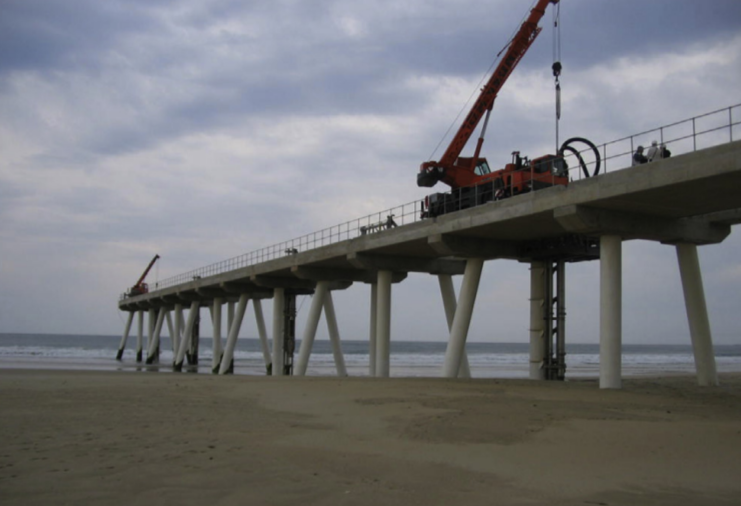
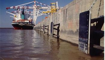
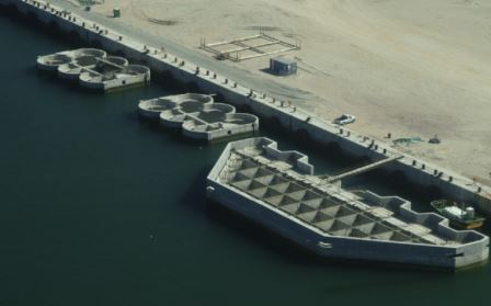
Reinforced Concrete (RC) is widely used in the marine environment, and in its various forms permits the construction of coastal facilities, including docks and harbours, quays, jetties, wharves, seawalls, pipelines, tunnels, and so on, which in turn facilitate on-shore and near-shore developments. It is also a popular choice for infrastructure of coastal cities, such as bridges, residential structures, warehouses and administrative institutions. Concrete will continue to be the construction material of choice for use in marine environments, as well as in a range of other demanding environments, into the foreseeable future. At this stage, there is simply no other viable alternative [3].
Chloride induced corrosion of reinforcement steel is the leading cause of deterioration of reinforced concrete structures in marine environment [4], reducing the service-life of such infrastructures. The annual cost of corrosion in India is 3% to 4% of the Gross Domestic Product (GDP) [5]. This loss can be avoided by adopting “performance based durability design” [6, 7] with a specific target service-life which serves to be economically most profitable and adds value to the project.

Figure 1: Coastal states in India
2 Concrete Durability
Concrete durability problems arise from the aggressiveness of the environment to which the structure is exposed. Different exposure conditions in the marine environment is shown in Fig. 2. Such exposure promotes chloride induced corrosion of reinforcement steel.

Figure 2: Exposure conditions in the marine environment [8]
The main reasons for such durability problems are the interconnected porous nature of the hydrated cement paste.
In the construction industry, durability is expected to be achieved through strength. But there is no simple or unique relationship between strength and any of the durability parameters [9, 10]. For example, a given grade of concrete made with different binders types say pure Ordinary Portland Cement (OPC) or OPC blended with Supplementary Cementitious Material (SCM) will have different durability property (database [11]), but same strength. The key to concrete durability is the achievement of a “designed concrete pore structure”. The unique way towards this goal is by specifying the concrete accurately for its intended purpose. The specification should address different aspects such as intended service-life, quantifiable description regarding serviceability requirement and failure, acceptable level of risk and possible extent of maintenance.
2.1 Conventional durability design
Conventionally, the durability design of a concrete structure for a target working life is achieved using a “prescriptive (deemed-to-satisfy) approach”. The prescriptive approach, based on acquired experiences and empirical data, provides the requirements for material composition and structural details for given environmental actions and target working lives. This approach is followed by most design codes in use (IS 456:2000 [12], IS 4651:2014-4 [13], IRC 112:2011 [14], IRS CBC:1997 [15]). The provisions include limits of
- Minimum cement content,
- Maximum water cement (w/c) ratio
- Minimum grade of concrete
- Nominal concrete cover
However, the fulfillment of a particular service-life (say 120 years), if all of these prescription are satisfied, cannot be quantified using this approach. In other word, if all requirements are satisfied, what will be the achieved service-life? Further this approach neither quantifies what constitutes the end of service-life. To provide solution to such a question, there is an increasing demand to incorporate more advanced concepts related to concrete durability, due the need to better foresee and prevent distresses, in particular the corrosion of the reinforcement.
3 Performance based durability design
The corrosion process in concrete is highly complex with various physical-chemical interactions among saline solutions, solid phases of concrete and moisture. The complicated nature of the process leads to significant uncertainty when modelling corrosion [16]. In addition there is significant uncertainty associated with some of the parameters which dictate corrosion initiation, such as the time dependent diffusion coefficient, the critical chloride content and the provided concrete cover [6, 7]. The presence of such engineering uncertainty necessitates the adoption of “performance-based approach” for design. The performance-based approach involves modelling the real ageing process of structural materials under environmental actions and employs mathematical models to evaluate the required properties and structural dimensions for expected design lives through probabilistic treatments. These methods allow the uncertainty associated with all levels of corrosion process to be incorporated into the analysis, leading to a robust and informed design. The performance-based approach is an ‘engineered approach’ to durability design.
Considering structural design of durability for corrosion processes, the design factors are listed in Table 1 as concrete cover quality (diffusivity), concrete cover thickness, and crack control criteria. The concrete cover quality and thickness are designed through the durability models with the target service lives and appropriate DLS adopted. For the performance design procedure, the concrete surface is supposed to be exposed directly to aggressive agents (Cl−). The model-based design follows a reliability analysis format with a target probability of failure, PT [6].
Table 1: Durability Requirements
| Material | Structural |
| w/c ratio cement type cement content | cover quality cover thickness crack control |
3.1 Design Life and Durability Limit State
The asset owner desires a working life of 120 years for a particular port concrete facility. Aiming for this target, the durability design should first decide the working lives for each elements on the basis of their structural importance and technical feasibility. The basis being that the principal elements have the same working life as the whole project (120 years), whereas the secondary or replaceable elements can be shorter. For these elements the maintenance and replacement schemes should be specified in the design phase.
Durability Limit States (DLS) are needed for quantitative durability design using the performance-based approach. These are the minimum acceptable performance levels for different durability processes. For corrosion process, two DLS can be defined: (a) corrosion initiation state, and (b) corrosion to an acceptable extent. As an example IRS CBC:1997 [15] specifies that under external loads the permitted design crack width can be 0.1 mm or 0.2 mm depending on exposure condition, for Reinforced Concrete (RC) elements. Whereas no cracking is permitted for Prestressed Concrete (PC) components. In a marine port project, PC elements, principal RC elements, and RC elements with high maintenance difficulty should adopt DLS (a), while secondary RC elements may adopt DLS (b). The stages in life of a corroding concrete element is shown in Fig. 3 [6] for visualising various DLS.

Figure 3: Schematic description of phases in corroding concrete
3.2 Corrosion deterioration model
The design model for chloride-induced corrosion is adapted from the analytical model of diffusion. With the DLS specified as the corrosion initiation state (a), the design equation can be written as [6],
G = Cth − C(Cs, xd, Dc, TSL) (1)
The objective being to obtain cover thickness (xd) and specifications of the concrete such as the chloride diffusion coefficient of concrete (Dc) for the specified design life (TSL = 120 years) subject to
P (G < 0) ≤ PT (2)
C( ) is the chloride concentration function in concrete. This model has four governing parameters
- Threshold chloride concentration (Cth)
- Concrete surface chloride concentration (Cs)
- Chloride diffusion coefficient of concrete (Dc)
- Concrete cover thickness (xd)
3.3 Preliminary Design
These four parameters have significant dispersion for a given exposure condition, and their statistical nature must be taken into account to guarantee a large enough safety margin for the durability design. As mentioned earlier, the target probability of failure is fixed as PT for the design at this stage. Towards this aim, the design is performed by a full probabilistic scheme using directly the statistical properties of the parameters.
The statistical properties of model parameters are analysed on the basis of the long-term in-place structural investigations and exposure tests conducted in the vicinity of the proposed project in the past or based on literature. It is advised to identify these parameters and must be included in the feasibility investigation for the project. The investigation comprises of environmental data extracted from site investigation for atmospheric temperature, humidity, and air-borne chloride content and wind speed. Further, the evaluation of chloride/carbonation profiles of structures in the vicinity of the proposed project or similar projects elsewhere must be incorporated. This investigation helps to statistically characterise the diffusive property of concrete and evaluate the distribution of surface chloride concentration. Since the concrete cover is the only structural parameter in the design equation, correct specification of concrete cover thickness is the central issue for durability design. The statistical properties of concrete cover thickness are important for correct estimation of reliability with respect to the design equation, and are related closely to the construction methods and practice. Statistical analysis based on the data of achieved cover thickness of similar concrete infrastructures must be investigated or tolerance prescribed by the codes may be used.
3.4 Design assisted by testing
Based on the preliminary design, the required construction material and specifications for executing the design can be used as design basis for the project. However, every project is unique and precise characteristic of the design are quantified by testing the material used at project site.
During the construction, the properties of structural concretes should be tested in on-site laboratory. In parallel, the constructed concrete elements, prefabricated or cast-in-place, are
inspected for the achieved quality, and particularly for the thickness of concrete over. These data provide the information on the realistic construction quality of concrete elements, thus help to update the statistical properties of parameters in the durability assessment models. The measurements of concrete cover thickness for the cast-in-place concrete elements are done either through, ground penetrating radar, electromagnetic test, ultrasonic and radiography.
The in-situ data of chloride diffusion coefficient of structural concretes are to be collected from the on-site laboratories for different concrete elements. The chloride diffusion coefficients are measured on structural concretes under standard conditions by rapid migration method [17]. The concrete surface chlorides are tested as per [18] and airbourne chlorides is obtained form [19]. The critical threshold chloride concentration is evaluated by the accelerated chloride threshold testing [20]. Additions of admixtures such as ground granulated blast furnace slag, fly ash, silica fume and metakaolin alter the properties of ordinary portland cement concrete. Test- ing of such concrete is therefore crucial to study its chloride ingress property and statistically characterise it to apply in the performance-based design.
This updated data source, form the essential basis for predicting the durability performance of concrete elements during its service-life.


3.5 Monitoring and Maintenance Planning
The maintenance planning is to establish the techniques and intervention periods of maintenance, on the basis of the durability states of the concrete elements. The strategies of maintenance planning is to be preventive/proactive, which refers to the intervention at early stage of deterioration, normally at low maintenance costs. During the service-life, the deterioration processes will be monitored via periodical inspection and sensors. The maintenance actions are to be taken at early stage of deterioration for elements with the help of these inspections and monitoring. Since concrete elements are designed in such a way that the probability of corrosion initiation (PT ) will only be exceeded after 120 years, technically all elements can be exempted from maintenance during the service-life. However, given the uncertainty associated with the concrete construction, e.g. early-age cracking, unintended lower concrete cover, accidental use of saline water for concrete mixing and/or curing and the unexpected environmental actions during service-life, e.g. the global warming and long-term change of ambience, a basic maintenance planning is necessary for concrete elements. Through monitoring of as-built concrete components it is possible to establish the service-life of the casted components in real-time.
The basic maintenance planning considers mainly two aspects: the durability performance monitoring, and maintenance of the elements. Monitoring involves: potential mapping, resistiv- ity mapping, embedded anode sensors, cover thickness measurement, air permeability, chloride profile, etc. It is also beneficial to cast test concrete elements near the actual structures so that monitoring can be done on them rather than the actual components. The maintenance scheme consists of performing the surface chloride extraction by electrochemical method or a cathodic protection system can be installed to protect the steel bars against the unexpected durability failure. It should be noted that this basic maintenance scheme is to interact with the durability inspection/monitoring data and the real-time durability assessment during the service-life. A predictive maintenance scheme is setup for the same.
3.6 Summary
In essence the performance-based approaches is fundamentally a measurement and verification design procedure. Fig. 4 [6] provides a schematic of this performance-based approach.

Figure 4: Schematic representation of the performance-based approach
4 Case study
As requirement for a new concrete harbour, a service life of 120 years is specified for a caisson quay wall. The part of the caisson facing the tidal zone is the most prone to corrosion initiation.
4.1 Conventional strategy
As per IS 456:2000 [12], the exposure condition can be considered to be “Extreme”. The “durability design” for Extreme exposure according to current prescriptive provisions of IS 456:2000 [12] are:
- Minimum nominal cover : 75 mm
- Minimum cement content : 360 kg/m3
- Maximum cement content : 450 kg/m3
- Max w/c ratio : 0.4
- Aggregates : 20 mm nominal maximum aggregate size complying IS 383:2016 [21]
- Min concrete grade : M40
As highlighted previously, by satisfying all the prescriptive requirements the following important aspects remain unanswered:
- Actual achieved service-life
- How to consider Global Warming effect
- Recommendation on type of cement
4.2 Performance based strategy
In this section two tasks will be undertaken:
- The prescriptive durability design will be benchmarked using the performance based design to calculate the actual achieved service life.
- Actual performance calculation will be done to design the caisson for 120 years.
The target probability of failure is PT = 0.10, which corresponds to a target reliability indexβT = 1.3. The governing parameters of the design are probabilistically quantified as follows:
- Chloride load: A chloride surface concentration is a Gaussian parameter having mean 5.5
- % weight of cement with 1.3 % weight of cement as standard deviation [22].
- Critical chloride: A critical chloride concentration at reinforcement level for corrosion initiation is 0.6 % weight of cement and 0.15 % weight of cement as standard deviation. This is a Beta distributed variable with limits of 0.2 and 2 % weight of cement [23].
- Chloride diffusion: For comparison two types of concretes varying only in cement types viz. OPC and OPC+Slag SCM, but same w/c=0.4. The chloride diffusion values are sourced from database [11]
- Global warming: At present the average temperature at the site is 27.83 ◦C with a standard deviation of 2.7 ◦C. Future anthropogenic emissions of greenhouse gases and aerosol particles would cause climate change and temperature rise. In the IPCC Fifth Assessment Report released in 2014 [24], some climate change scenarios were simulated and referred to “Representative Concentration Pathways” (RCPs). In the present project a medium stabilisation scenarios (RCP 4.5) is considered.
- Clear cover: The concrete cover is 75 mm with standard deviation of 6 mm, which implies execution requirements targeted. This is a Beta distributed variable [23]. Based of the design a revised cover is adopted.
4.2.1 Results
Fig. 5 shows reliability plot and service-life achieved by using OPC cement and using the conventional approach. The achieved service-life is 5.48 years. This is far from achieving

Figure 5: Benchmark of conventional approach with OPC concrete and 75 mm cover
even a life of 10 years let alone achieve a life of 120 years. Fig. 6 shows reliability plot and service-life achieved by using OPC+SCM cement and using the conventional approach. This shows that the achieved life is 46.4 years which is more than the previous analysis but still far from achieving a life of 120 years. This highlights the importance of the performance based “design”. Fig. 7 shows reliability plot and service-life achieved by using OPC+SCM cement and using the performance based approach, the service-life achieved is 120.58 years.

Figure 6: Benchmark of conventional approach with OPC+SCM concrete and 75 mm cover

Figure 7: Performance design for 120 years service-life
The performance approach offers following advantages:
- Quantification of achieved service-life for any design
- Design modification under non-compliance of actual service-life
- Allows choosing of concrete types
- Incorporates climate change which manifest over the long service-life
- Allows practically for the non-maintenance of the infrastructure
- Design option of using stainless steel, lower w/c concretes and other SCMs is also possible through which further reduction of concrete cover is possible
- Decisions can be based on life-cycle cost assessment
5 Inclusion in Tender document
In the present scenario, asset owners of coastal ports specify the conventional prescriptive requirements as per code in the design basis report. However, they wish to know how much really is the achieved service-life and what can be done to have a “major” maintenance free life. It is necessary that the change should begin at tendering stage of the project.
The tender document should mandate the requirement to study the durability factors and incorporate in the feasibility exercise, to evaluate all the environmental parameters responsible for degradation, including review of previous statistics for similar projects elsewhere. This will be the design basis for the preliminary performance-based design. The asset owner must emphasise on specific durability limit state as per their requirement and mention the expected service-life and target probability of failure. Testing of in-situ components along with the magnitude of tests to be performed are necessary part of the design basis. The asset owner must press for the requirement of probabilistic durability design in the tender document with a design report. And finally long term monitoring and updating of actual service-life must be included as part of the contract.
6 Conclusions
There is massive capital investment on coastal infrastructure in our country. To safeguard these investments and avoid costly repairs and renovation due to premature deterioration of RC structures, it is prudent to verify the properties of concrete cover (its penetrability and thickness). This technical article recommends the change of approach to the asset owners/concrete industry from traditional prescriptive approach to the performance-based specifications. It highlights important steps involved in the durability design of concrete components with a case study. It is recommended to bring about a change of approach from the tendering stage itself. The applicability of this technology is universal, both for new infrastructures [6, 7] as well as for repairing the existing assets [25].
References
- UN Atlas. 44 percent of us live in coastal areas. http://coastalchallenges.wordpress.com, 2010. Retrieved January, 2019.
- Sagarmala. Impact from Sagarmala – 2025. http://sagarmala.gov.in. Retrieved Jan- uary, 2019.
- K Scrivener. Options for the future of cement. The Indian Concrete Journal, 88(7):11–21, 2014.
- A. A. Almusallam, A. S. Al-Gahtani, A. R. Aziz, F. H. Dakhil, and Rasheeduzzafar. Effect of reinforcement corrosion on flexural behavior of concrete slabs. ASCE Journal of Materials in Civil Engineering, 8(3):123–127, 1996.
- N. G. Thompson, M. Yunovich, and D. Dunmire. Cost of corrosion and corrosion mainte- nance strategies. Corrosion Reviews, 25:247–261, 2007.
- S. A. Faroz. Performance Based Durability Design of Bridges for 120 Years. Indian Society of Structural Engineers (ISSE) Journal, 20(3):10–15, 2018.
- S. A. Faroz. Durability Design Methodology of Metro Rail Bridges for 120 Years. Metro Rail News, 2:26–31, 2018.
- BS. BS 6349-1 Maritime Structures Part 1: Code of Practice for General Criteria. British Standards, London, UK, 2000.
- A. Neville. Consideration of durability of concrete structures: Past, present and future.
- Materials and Structures, 34:114–118, 2001.
- R. N. Swamy. Sustainable concrete for the 21st century concept of strength through durability. http://www.jsce.or.jp. Last accessed: January, 2019.
- DARTS. Durable and Reliable Tunnel Structures: Data. Technical report, European Commission, Growths 2000, 2004.
- BIS. IS 456 Indian Standard for Plain and Reinforced Concrete – Code of Practice. Bureau of Indian Standards, New Delhi, India, 2000.
- BIS. IS 4651-4 Indian standard for Code of practice for planning and design of ports and harbour: Part 4 General design consideration. Bureau of Indian Standards, New Delhi, India, 2014.
- IRC. IRC 112 Code of Practice for Concrete Road Bridges. Indian Roads Congress, India, 2011.
- IRS. IRC CBC Code of practice for Plain, Reinforced & Prestressed Concrete for General Bridge Construction. Research Designs and Standards Organisation, Lucknow, India, 1997.
- S. A. Faroz. Assessment and Prognosis of Corroding Reinforced Concrete Structures through Bayesian Inference. PhD thesis, Indian Institute of Technology Bombay, Mumbai, India, 2017.
- NT. NT Build 492 Concrete, Mortar and Cement Based Repair Materials: Chloride Mi- gration Coefficient from Non-Steady-State Migration Experiments. Nordtest Method, 1999.
- NT. NT Build 443 Concrete, Hardened: Accelerated Chloride Penetration. Nordtest Method, 1995.
- ASTM. ASTM G140 – 02 Standard Test Method for Determining Atmospheric Chloride Deposition Rate by Wet Candle Method. ASTM International, USA, 2014.
- D. Trejo and R. Pillai. Accelerated Chloride Threshold Testing: Part I – ASTM A 615 and A 706 Reinforcement. ACI Materials Journal, 100(6):519–527, 2003.
- BIS. IS 383 : 2016 Coarse and Fine Aggregates for Concrete – Specifications. Bureau of Indian Standards, New Delhi, India, 2016.
- O.E. Gjorv. Durability design and quality assurance of major concrete infrastructure. Advances in Concrete Construction, 1(1):45–63, 2013.
- fib. Model Code for Service Life Design. Federation Internationale des B´etons, Lausanne, Switzerland, 2006.
- IPCC. Fifth assessment report of the intergovernmental panel in climate change. Cam- bridge University Press, London, 2014.
Author


