
Technical Manager
Dextra
Reinforced concrete design and construction practice has historically focused on the use of bonded straight or bended rebar as a method for rebar anchorage. This relies on bond integrity between the rebar and the concrete so that sufficient anchorage strength is obtained. However, a bonded straight or bent length of rebar is not always the most effective or efficient anchorage method, and there are many situations where the use of headed bars, sometimes called headed reinforcement anchors or “T” bars, is more desirable from a design perspective, more convenient from a construction perspective, or both.
Headed bars are used as an alternative to the more traditional means of reinforcement anchorage. The load from the rebar is anchored via a head bearing or a combination of head bearing and rebar bond.

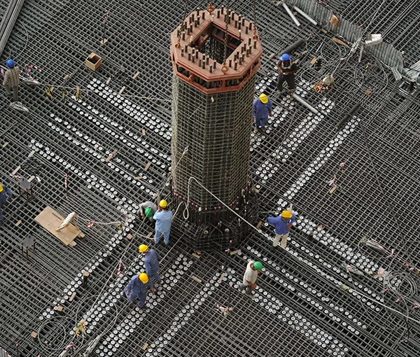
The advantages of using headed bars are particularly apparent in heavily reinforced concrete, where rebar congestion and constructability are often problems. As a result, their use is now becoming more widespread around the world, particularly within the civil infrastructure and nuclear new build sectors. Recent nuclear power plants where headed bars have been used include Taishan 1 China, Hinkley Point C UK, Akkuyu Turkey, Flamanville France, Kursk Russia and Ruppar Bangladesh.
In a heavily reinforced concrete element, there is often insufficient space for a straight or bent length anchorage. In addition, a bent anchorage often causes additional rebar congestion problems. The use of headed bars eliminates the requirement for a bent anchorage and allows the reduction of the bond/development length. In certain circumstances (code provisions permitting), they allow the elimination of a required bonded rebar anchorage (development) length altogether. The resultant reduction in congestion facilitates concrete consolidation. The transportation of straight lengths of rebar incorporating headed bars is easier than transporting rebar with bent anchorages and on-site handling and fixing also becomes easier. The use of headed bars can therefore offer a distinct time and cost advantage as well as a potential improvement in concrete quality.

(a) ACI 318 90° hook. ldh = Tension development length
(b) ACI 318 180° hook. ldh = Tension development length
(c) ACI 318 headed bar. ldt = Tension development length
(d) Headed bar not requiring a bond/development length. Subject to certain criteria and code provisions
Applications
Headed bars can be used for a variety of applications including beam-column joints, knee joints, pile caps, column-roof slab connections, to the end of cantilever elements, within corbels, for transverse shear reinforcement and for shear wall cross ties. Their use can be broken down as follows:
(a) The termination of main longitudinal reinforcement, where the development length associated with a straight or bent bar anchorage would be an issue, or where there is rebar congestion. As a result, larger rebar diameters are usually associated with this application.
(b) The termination of transverse shear reinforcement. The use of headed bars for this application is usually associated with the ease of construction. This is particularly the case for seismically designed structures where code provisions require bends greater than 90° (typically 135°), and where for quality control purposes, uncontrolled, on-site manual bending, or re-bending (to fit the rebar into position), is not allowed. These applications are therefore usually associated with smaller rebar diameters (typically 10- 20mm) and of particular benefit for the shear reinforcement of thick slabs or rafts, where the headed bar can simply be dropped down into position and tied to the top layer of longitudinal reinforcement, see Figures 5 and 6.


Research into the use and effectiveness of headed bars has been conducted for well over two decades. As a result, design provisions within codes of practice have increased and the use of headed bars has become more widespread. However, some codes of practice often take a decade or longer between major updates. Therefore, there is often a delay between unambiguous research findings and codified provisions. This has largely been the case for the use of headed bars as shear reinforcement.
The academic paper, Shear Strength and Behaviour of RC Structures with T Headed bars for Shear Reinforcement1, investigates the use of small ACI 3182 compliant headed bars in beams used as shear reinforcement in safety critical nuclear facilities. The main conclusions are that:
- “Specimens with T-headed bars as shear reinforcement had marginally better behavior and shear strength than the companion specimens with conventional stirrups.”
- “Replacing conventional stirrups with T-headed bars as shear reinforcement doesn’t have a detrimental influence on the behavior of the structure.”
- The shear strength of doubly reinforced (>2% tension and compression reinforcement ratio) concrete structures with T-headed bars as shear reinforcement can be predicted conservatively using ACI 3493 code recommendation.”
Another extensive study by the Electrical Power Research Institute, entitled Advanced Nuclear Technology: Use of High Strength Headed Bars as Shear Reinforcement for Structural Concrete4, tested 39 beams with a span to depth ratio of 3 with Grade 550 reinforcement and headed bars. Each head was of a small ACI 318 compliant size and used at both ends of straight transverse reinforcement. The beams differed in their headed bar anchorage positioning. The study concludes that:
- “Adequately anchored headed deformed bars provide shear strengths that are equivalent to hooked stirrups. Furthermore, strain measurements taken near the anchorage points of the shear reinforcement indicate both types of anchorage are capable of developing yield strains in the reinforcement.”
- “Headed bars used as shear reinforcement are adequately anchored when placed (1) in direct contact between the bearing face of the head with longitudinal reinforcement or (2) inside at least one longitudinal bar and providing side concrete cover to the headed bar of at least six headed bar diameters. Placing headed bars outside of longitudinal reinforcement and close to the side of a member may result in reduced shear strength.”
- “Grade 80 [Grade 550] shear reinforcement provides the same strength and similar
serviceability as Grade 60 [Grade 420] shear reinforcement.” - “Low strengths relative to the nominal strength calculated using the provisions of ACI 318-14 occurred for specimens with ρtfytm below 80 psi [550 kPa]. This finding indicates that the value of the minimum shear reinforcement prescribed in ACI 318-14 should be re-evaluated.”
- “Shear crack widths increase with beam depth.”
Note that ACI 318 was modified in 2019, after this study was published.
(c) Other applications include their use as an alternative to a standard rebar lap or rebar coupler splice by using overlapping heads, as well as their use as confinement, torsional, and punching reinforcement.
Codes of Practice
Indian Standards
With regards rebar anchorage, the Indian concrete code of practice IS 4565, and the design handbook SP 346, both allow the use of headed bars. They state that “any mechanical or other device capable of developing the strength of the bar without damage to concrete may be used as anchorage with the approval of the engineer-in-charge.” (Clauses 26.2.2.3 and 3.3.4 respectively).
However, no explicit rules or guidance is provided for designing with headed bars. When designing to IS 456 and SP 34, it is therefore necessary to look to other design standards for guidance.
The Indian standard IRC 112-20117 Code of Practice for Concrete Road Bridges, under the section for the anchorage of longitudinal reinforcement states that “Where mechanical devices are used, their effectiveness shall be proven and capacity to transmit the concentrated force at the anchorage shall be established by tests” (Clause 15.2.4.1 (2)). In addition, section 15.2.6 gives additional rules for high yield strength deformed bars exceeding 32mm in diameter, and states that “Splitting forces are higher and dowel action is greater with the use of large diameter bars. Such bars should be anchored with mechanical devices. As an alternative they may be anchored as straight bars, but links should be provided as confining reinforcement.”
Again, no explicit rules or guidance is provided for designing with headed bars. However, given that this code of practice is in part derived from EN 1992-1-1: 2014 Eurocode 28: Design of Concrete Structures; Part 1 – General rules and rules for buildings (henceforth referred to as Eurocode 2), a similar, if slightly modified approach can be taken to that outlined in the below Eurocode 2 section. In particular, IRC 112 section 16.11 deals with concentrated forces in the concrete resulting from a relatively small highly loaded area, which can be compared directly to Eurocode 2, section 6.7, and forms the basis of the fundamental head capacity as described below.
Other Worldwide Codes of Practice
Codes of practice which give explicit information about how to design using headed bars include:
- ACI 318-19 Building code requirements for structural concrete
- FIB Model Code 20109
- AS 3600-2018 Australian Standard Concrete Structures10
- GB 50010-2002 National Standard of the People’s Republic of China, Code for Design of Concrete Structures11
Some other codes, including Eurocode 2, allow the use of headed bars or “mechanical devices” for anchorage, but give no explicit information about how to design with headed bars. However, rules can often be derived from various clauses within the text of the standards, particularly those related to high compressive (bearing stress) applied via a relatively limited bearing area.
Eurocode 2 and ACI 318 are both commonly used codes of practice worldwide.
EN 1992-1-1 (Eurocode 2 Part 1-1)
Although Eurocode 2 gives no explicit rules for designing with headed bars, it allows their use for the anchorage of reinforcement. Clause 8.8, which lists additional rules for large diameter bars states that “Splitting forces are higher and dowel action is greater with the use of large diameter bars. Such bars should be anchored with mechanical devices. As an alternative they may be anchored as straight bars, but links should be provided as confinement reinforcement.”
The document Dextra Manufacturing, Design Guide, Methodology for Designing with Headed Reinforcement Anchors to Eurocode 212 sets out rules for designing with headed bars based primarily on the provisions within Eurocode 2. Eurocode 2 Clause 6.4, which deals with partially loaded areas, is used for the basis of calculating the fundamental head capacity. The guide is written by the consultant engineers Arup and is intended to be “used as a non-contradictory supplement to EC2 ” (Section 1.2).

Figure 7. Eurocode 2 Headed Bar Design Guide Figure 8. Dextra Calculation tool based on the Design Guide
Eurocode 2, as implemented by the aforementioned design guide, allows the calculation of the minimum headed bar center to center distance and minimum distance to the edge of the concrete, for any given head size, concrete strength, and grade of rebar. It also allows the calculation of the associated transverse bursting force under the head and transverse confinement reinforcement to resist the bursting force. If the head bearing area is large enough, the concrete strong enough and the spacing and edge distances sufficient, the guide allows the full rebar design load to be taken via head bearing alone. In other cases, the rebar design load can be taken via a combination of head bearing and a rebar bond (development) length.
As a result of working from first principles, the resultant design parameters are often less conservative than some more prescriptive codes of practice, where for example a minimum head bearing area or minimum concrete strength is considered for every case irrespective of the actual size of head used, or the actual concrete strength specified.
Although the principles of the guide are applicable to any shape of head where the rebar is concentrically attached to the head and there is a flat bearing area perpendicular to the longitudinal axis of the bar, the detailed information is applicable to round heads only. The guide highlights where each is the case.
The guide does not consider the performance of the headed bar itself but rather the concrete’s ability to resist the load from the headed bar. A headed bar product standard should therefore be used for product performance assessment. ISO 1569813 is one such product standard and this product standard forms the basis of the European Assessment Document EAD 160012-00-030114, from which a European Technical Assessment (ETA) and CE marking can be granted. With regards the anchorage of longitudinal reinforcement Eurocode 2 states “where mechanical devices are used the test requirements should be in accordance with the relevant product standard or European Technical Approval” (Clause 8.4.1 (5)).
ACI 318-19
ACI 318 gives a set of provisions for designing with headed bars which are primarily based on test data over many years. It allows the use of a relatively small head, which has a net bearing area at least four times that of the bar cross sectional area (4A) and where “the force in the bar is transferred to the concrete through a combination of bearing force at the head and bond forces along the bar.” (Clause R25.4.4). Despite there being a rebar bond/development length requirement, there is still a clear advantage compared with standard hooked bars. Clause R25.4.3 states “For bars in tension, heads allow the bars to be developed in a shorter length than required for standard hooks, but otherwise perform in a similar manner (Thompson et al. 2005, 2006a, b; Shao et al. 2016)”.
Prior to the 2019 version of the standard, there was a restriction on the maximum concrete and rebar strengths allowed, which considerably restricted the use of headed bars. However, these restrictions have now been removed. The restriction of bar diameter to a maximum of 36mm remains, which is based on a lack of data for larger bar diameters. However, test programs using large bar diameters are ongoing.
In all cases the minimum center to center and minimum edge distances are set as multiples of the bar diameter, with the bond/development length varying, being a function of rebar and concrete strength together with four modification factors. Diagrams are provided to show how a concrete cone break out failure can be precluded in joints.
For beam-column joints of special moment frames forming part of the seismic force restraint system and for Seismic Design Categories (SDG) B through to F, the development length should be increased by multiplying the specified rebar yield strength by 1.25. “The factor 1.25 is intended to represent the potential increase in stresses due to inelastic response, including strain hardening that may occur in beams of special moment frames” (Clause R18.8.5.2).
With regards the product standard for headed bars, ACI 318-19 requires that the heads are compliant with the provisions of ASTM A97015 Class HA.

Compression Forces
Where headed bars are subjected to compression loading care should be taken to avoid the concrete beyond the head being overstressed resulting in a punching shear cone failure as shown in Figure 9(a). One solution is to ensure there is sufficient bonded length within the anchorage zone to resist the compression forces, thus avoiding the head itself being loaded at all due to rebar compression forces, as shown in Figure 9(b).
ACI 318-19 does not permit the use of heads to contribute to compression anchorage. Likewise, it does not permit the use of bent bars to contribute to compression anchorage. Clause 25.4.1.2 states “Hooks and heads shall not be used to develop bars in compression”. As a result, compression loads should be resisted by the straight length of rebar before the head or bend.
Similarly, Eurocode 2 Clause 8.4.1 (3) states that “Bends and hooks do not contribute to compression anchorages”.
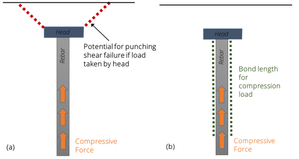
Figure 9. The head of a headed bars should not generally be used to take rebar compression forces
(a) Potential failure mechanism when compression forces are taken by the head.
(b) Headed bars taking compression forces, should generally rely on a bonded (development) length of rebar to transfer the compression forces into the concrete within the anchorage zone.
Although the straight length compression anchorage (development) length for hooked bars and headed bars is the same, there is an advantage in using headed bars for compression anchorages because the required bonded (development) length can start closer to the edge of the concrete, as shown in Figure 10.

Types of Headed Bar
Most headed bar manufacturers produce products with at least two sizes of head. The smaller typically has a net bearing area of at least four times the cross-sectional area of the bar, (a 4A head), to comply with the requirements of ACI-318, while the larger is typically 9A. 9A heads are usually selected because using this size can reduce the burden of ISO 15698 in concrete testing for static and fatigue loading qualification. Graphical representations of these two sizes can be seen in Figure 8.
The heads themselves are typically round, although some manufacturers produce square, rectangular and other shapes of head.
ACI 318 and ASTM A970 allow round, elliptical and rectangular shaped heads.
Eurocode 2, as implemented by the Arup/Dextra guide also allows different shapes of head, although the detailed calculations within the guide are given for round heads only. However, the shape of the head will dictate the shape of the overstressed region of concrete directly under the head. Therefore, for shapes other than round heads, the orientation of the head matters in keeping the regions of overstressed concrete separate. For typical head sizes, overlapping regions would require a reduction in stress on the head, leading to a requirement for a rebar bond/development length in front of the head, for cases where a bond (development) length was previously not required, or where a bond (development) length was previously required, an increase in this length. Non round heads may therefore require greater spacing than round heads with the equivalent net bearing area.


To comply with the requirements of ACI318, ASTM A970 and Eurocode 2, as implemented by the Arup/Dextra guide, the bearing area of a head must be flat and perpendicular to the longitudinal axis of the bar. In addition, there should be good concentricity between the head and the bar to ensure a uniform bearing stress distribution on the head. For products with poor concentricity a smaller effective bearing area should be considered, as shown in Figure 14.

Headed bars can be manufactured in many ways. These include a threaded connection between head and bar, a friction welded connection, a hot forged head from the bar itself, or a hot forged connection between a plate and the bar. Products which are hot forged from the bar itself are generally limited to smaller head sizes as larger head sizes are difficult to hot forge from the bar while retaining a flat bearing area perpendicular to the longitudinal axis of the bar. Typical round headed products can be seen in Figure 15.

(a) Cold forged and threaded bar end (Dextra Bartec/Fortec); (b) Extruded sleeve onto bar with threaded end (Dextra Griptec); (c) Round end plate with hot forged connection (Dextra PC Headed Bars)
Headed bars are usually attached or processed while the rebar is straight. While this generally isn’t a problem for longitudinal reinforcement, it becomes inefficient for transverse reinforcement if the bar needs to be bent after the attachment of the head. This is because transverse reinforcement is often processed via automatic cut and bend lines, referred to as automatic shear link cut and bend machines, where rebar goes into the machine straight and is preprogrammed to cut and bend the rebar to a predetermined shape.
One recent innovation for the manufacture of transverse headed bars / shear links is the Dextra Pressed Connection (PC) system, as illustrated in Figure 15(c). The system allows the shear link to be produced on an automatic cut and bend shear link line before being transferred to a separate, fully automatic machine for the application of the head. The end of the rebar is first heated, the round plate is put over the heated end and the bar end is forged or pressed to make the connection between the two.
Testing and Performance Requirements
A high and consistent level of product performance is of paramount importance. The product should be strong and robust with quality control measures put in place to ensure consistency of performance.
Some headed bar systems, for example the Dextra Griptec headed bar, as illustrated in Figure 15(b) have built in quality control features during processing. After the extrusion of a sleeve onto the bar end, the Griptec machine systematically proof loads each and every connection via a tensile test. The machine then automatically records the results of each processed sleeve.
The ductility of reinforcement is of significant importance, particularly in seismic design, with the reinforcement ductility requirements increasing as the requirement for energy dissipation increases as a result of greater seismic loading. The principal measure of rebar ductility is usually the percentage elongation at maximum force (Agt), which is a measure of the amount of permanent plastic deformation along the whole length of the bar, when tested in air. To achieve this ductility, the rebar must be taken to its maximum load carrying capacity. In cases where there can be no reduction of rebar ductility, headed bars should therefore be strong and robust enough so that failure does not occur at the head or connection, but rather in the parent rebar away from the head and any processed area of rebar.
ACI 318-19 requires headed bars to be compliant with the requirements of ASTM A970 Class HA. This requires mechanical testing in air to verify performance as well as periodic testing during manufacture.
ISO 15698 gives a number of performance categories. Testing for anchorage capacity, referenced Category B, under static loading is mandatory and broken down into three sub-categories, B1, B2 and B3, depending on the performance level. A robustness test for the head to bar connection is also mandatory. Optional tests are:
- Category F, tests high cycle elastic fatigue loading, with two sub-categories, F1 and F2.
- Category S, tests for low cycle elastic-plastic loading and is therefore suitable for members exposed to seismic loading.
As well as product qualification, the standard also covers production testing.
Summary
Headed bars are now a well-established method of rebar anchorage and codes of practice are being changed in line with the extensive research that has been carried out over the last few decades.
Heavy rebar congestion can lead to labour intensive site placement and potentially a reduction in concrete quality. Headed bars help to reduce rebar congestion, facilitating concrete consolidation, as well as being easier to handle and fix on site than traditional bent bar anchorages. The use of headed bars can therefore offer a distinct time and cost advantage as well as a potential improvement in concrete quality.
While ACI 318-19 gives a clear set of provisions for designing with headed bars, Eurocode 2 gives no explicit rules. Nevertheless, rules can be derived from the existing text. The Arup/Dextra Guide gives a detailed methodology for this process whereby the design load can be taken by head bearing alone or via a combination of head bearing and rebar bond, subject to various design parameters. ACI 318-19 states that the headed bar should comply with the product standard ASTM A970, while the product standard ISO 15698 is usually used in Europe.
The Indian code of practice IS 456 and IRC 112, as well as the design guide SP 34 allow the use of headed bars. IRC 112 has in part been derived from Eurocode 2. Therefore, the principles of the Arup/Dextra guide to designing with headed bars to Eurocode 2 could be implemented when IRC 112 is the applicable code of practice.
About Author
Based in the UK and with a degree in Civil Engineering, Richard has worked for Civil Engineering contractors, steel mills and manufacturers of construction products. With over 25 years of experience in the design of steel products for construction, Richard is a specialist in their design, manufacture, and use. Richard is currently the Technical Manager for Dextra having held the position for the past 7 years.
References
1YANG, VARMA, KREGER AND BRADT
Shear Strength and Behaviour of RC Structures with T Headed bars for Shear Reinforcement
Structural Mechanics in Reactor Technology (SMIRT). SMIRT23 Conference 2015 Manchester, UK.
2AMERICAN CONCRETE INSTITUTE
ACI Code 318-19 Building code requirements for structural concrete and commentary, ACI 2019.
3AMERICAN CONCRETE INSTITUTE
ACI Code 349 Code Requirements for Nuclear Safety-Related Concrete Structures and Commentary, ACI 2014
4Electrical Power Research Institute
Advanced Nuclear Technology: Use of high strength Headed Bars as Shear Reinforcement for Concrete Structures. EPRI, Paulo Alto, CA: 2017. 3002010489
5BUREAU OF INDIAN STANDARDS
IS 456: 2000 Plain and Reinforced Concrete – Code of Practice (fourth revision)
6BUREAU OF INDIAN STANDARDS
SP 34: 1987 Handbook on Concrete Reinforcement and Detailing
7INDIAN ROADS CONGRESS
IRC 112-2011 Code of Practice for Concrete Road Bridges
8BRITISH STANDARDS INSTITUTION. BS EN 1992-1-1: 2004
Eurocode 2: Design of concrete structures. Part 1. General rules and rules for buildings. BSI, 2014
9INTERNATIONAL FEDERATION FOR STRUCTURAL CONCRETE
Fib Model Code 2010. Ernst and Sohn, 2012
10STANDARDS AUSTRALIA
AS 3600 – 2018, Australian Standard Concrete Structures.
11NATIONAL STANDARD OF THE PEOPLE’S REPUBLIC OF CHINA
GB50010-2002 Code for Design of Concrete Structures
China Architecture and Building Press 2012
12DEXTRA MANUFACTURING
13INTERNATIONAL ORGANISATION FOR STANDARDIZATION
ISO 15698-1: 2012, Steel for the reinforcement of concrete – Headed bars – Part 1: requirements. ISO, 2012
INTERNATIONAL ORGANISATION FOR STANDARDIZATION
ISO 15698-2: 2012, Steel for the reinforcement of concrete – Headed bars – Part 2: test methods, ISO, 2012
14EOTA
European Assessment Document EAD 160012-00-0301 Headed Reinforcement Steel Bars; EOTA 2018
15AMERICAN SOCIETY OF TESTING AND MATERIALS
ASTM A970/A970M-18 Standard Specification for Headed Steel Bars for Concrete Reinforcement.
Design guide: Methodology for designing with headed reinforcement anchors to Eurocode 2.
Written by Arup, 2018
Dextra India
215 Atrium 2, Tower 2, Ground Floor, Unit no. 001, Andheri – Kurla Road, Hanuman Nagar, Andheri East 400059, Mumbai, India.
Phone: +91 22 2838 6294 ext 217 / +91 80 9746 1155
Email: bjog@dextragroup.com
Website: dextragroup.com