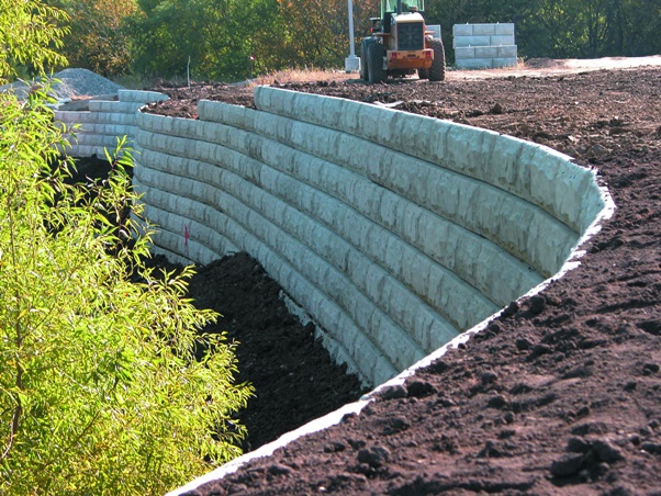
Mechanically stabilized earth (MSE or reinforced soil) is soil constructed with artificial reinforcing. It can be used for retaining walls, bridge abutments etc. MSE walls stabilize unstable slopes and retain the soil on steep slopes and under crest loads. The wall face is often of precast, segmental blocks, panels or geocells that can tolerate some differential movement. The walls are infilled with granular soil, with or without reinforcement, while retaining the backfill soil.
Reinforced Soil Slopes (RSS) are compacted fill embankments that incorporate the use of horizontal placement of geosynthetic reinforcement to create a stable, oversteepened slope structure. Oversteepened slopes often require facial geosynthetic wrap and wire forms for erosion control and constructability at the slope face.
Discussed in the article are the different advantages, components and design considerations of Mechanically stabilized earth wall and Reinforced Soil Slopes.
MSE Walls and their Application
The main advantages of MSE walls compared to conventional reinforced concrete walls are their ease of installation and quick construction. It also do not require formwork or curing and each layer is structurally sound as it is laid, reducing the need for support, scaffolding or cranes. They also do not require additional work on the facing.
Mechanically Stabilized Earth Wall (MSEW)
- Defined as wall formed by compacting the earth with the inclusion of layers of reinforcement in it.
- Given by Henrividal in 1960
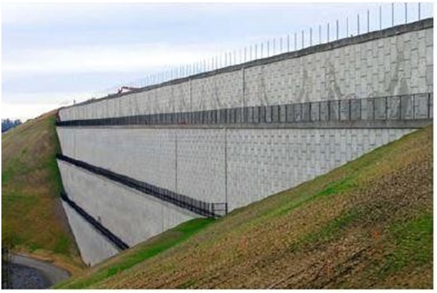
Application or Area of Use
- Use to retain soil, where stable side slope cannot be formed.
- An alternate to reinforced concrete and retaining walls.
- Either be temporary (life less than 36 months) or Permanent (75 or 100 years of life).
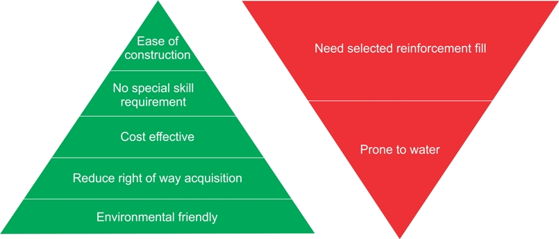
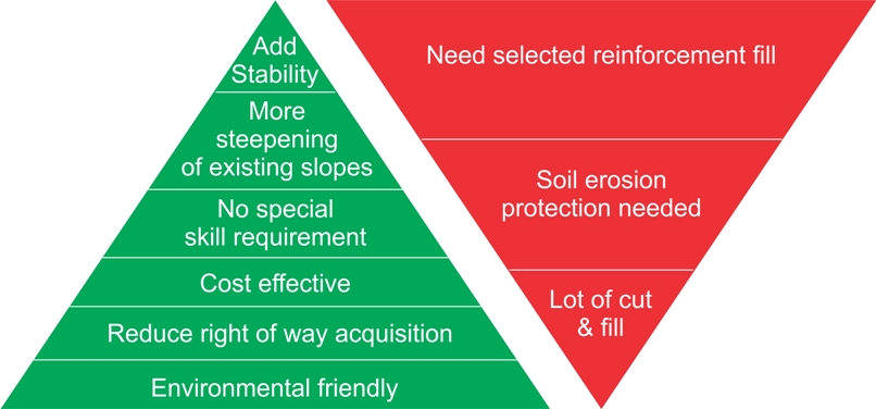
Pros and Cons of MSE walls
Components of MSE walls

Reinforced Soil Fill
- Fill material in which reinforcements are placed
- Consist of two components
- Earth
- Reinforcement
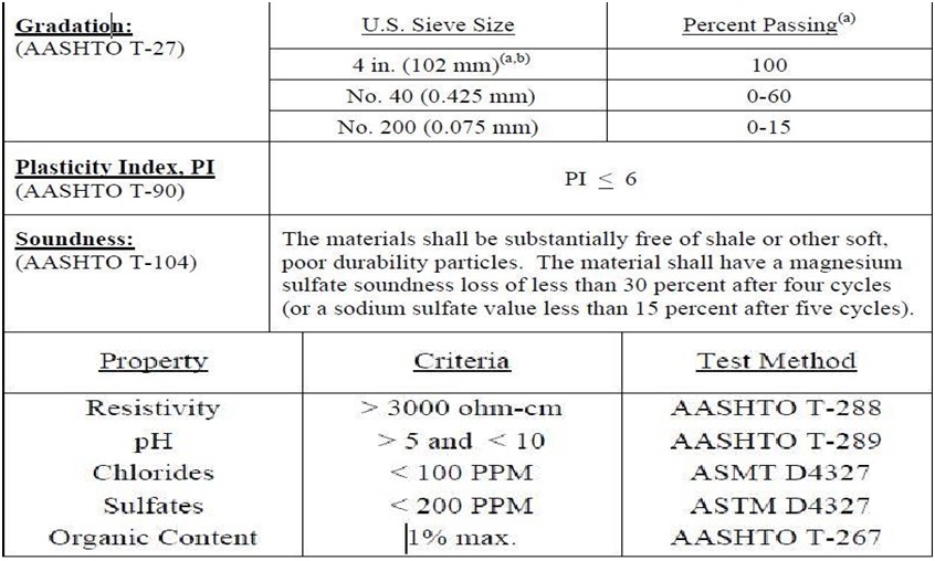
Properties of Reinforced Earth
Reinforcement

Facing
Facing system is divided into two types:
- Flexible Facing System

Geosynthetics 
Gabions 
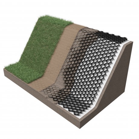
Geogrid 
Wire Mesh
- Flexible Facing System

Modular block wall unit 
Precast segmental panels
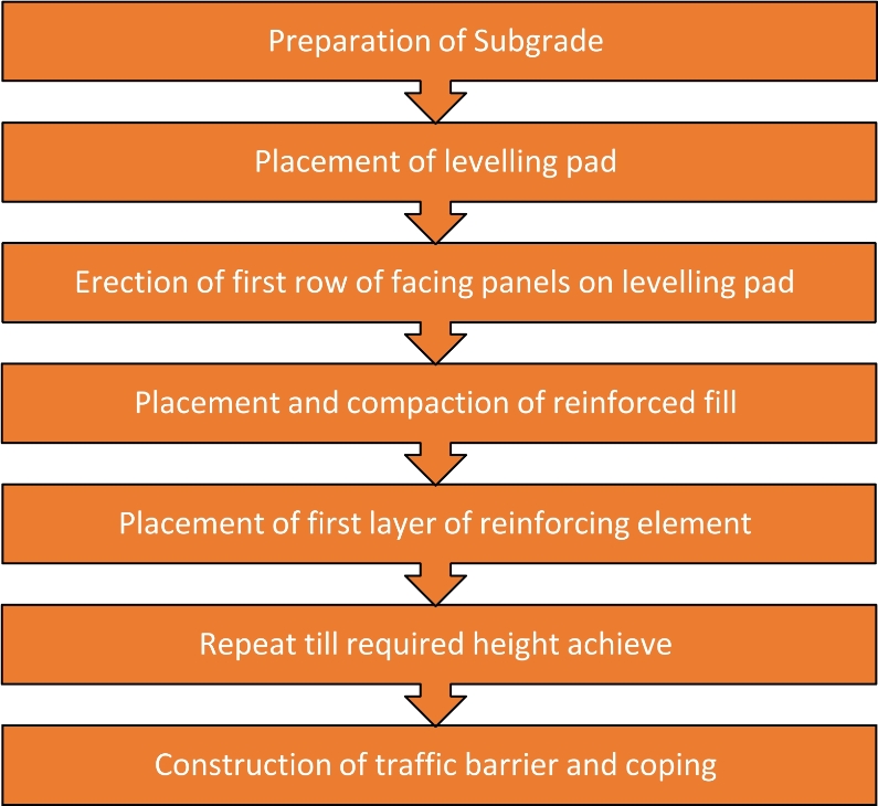
Construction Sequence
Design Sequence
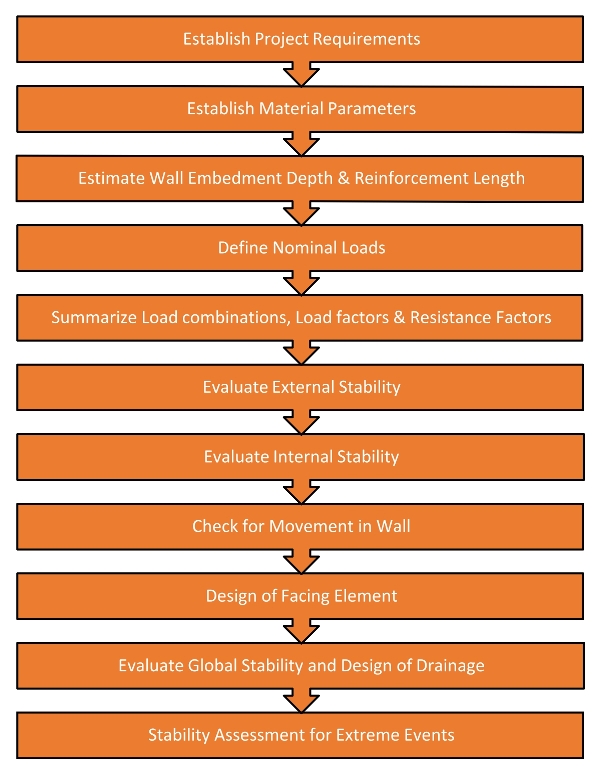
Checks for Stability
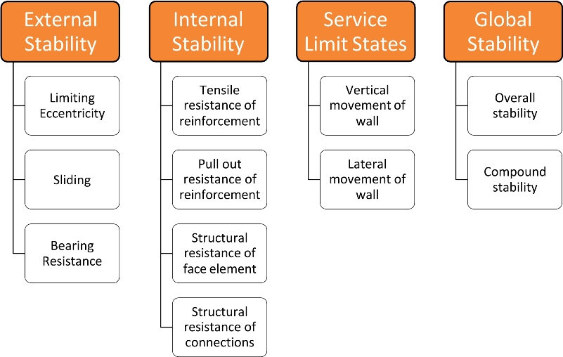
Project Requirements
Parameters needed before proceeding for design
- Geometry (wall height, wall batter, back slope, toe slope)
- Loading Conditions
- Performance Criteria
Material Parameters
Material parameters needed like Cohesion (c), Internal frictional angle (ɸ), Density, etc. for
- Foundation Soil
- Retained Fill
- Reinforced Fill
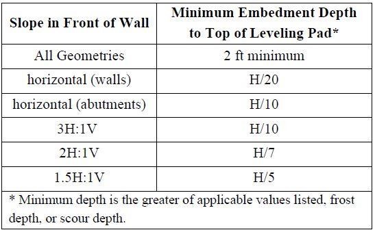
Wall Embedment Depth & Reinforcement Length
• Reinforcement length greater of 0.7H or 2.5m is taken.
• Although can go up to 1.1H, depends on structural parameters provided in table 2.1.
• Minimum Embedment depth of 0.6m is taken as minimum.
Nominal Loads
Three type of backfill placements:
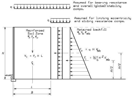
The active earth pressure for horizontal backfill is calculated using Rankine theory:

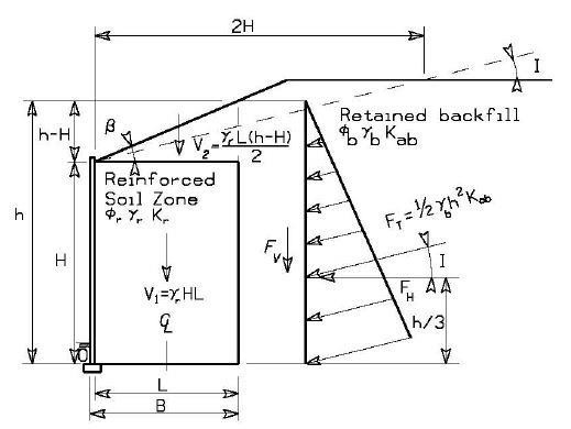
For sloping backfill or broken backfill case, active earth pressure is calculated using coulomb theory:

Also valid for battered walls with angle more than 10 degree.
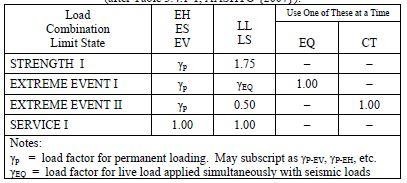
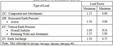
Load Combinations & Factors
The geometry is checked for every possible load combination to obtain max values of driving forces and minimum value of resistance forces.
External Stability
Sliding Check
- No sliding will occur if CDF ≥ 1.
- Here CDF is the ratio of resisting factored forces to that of driving factored forces.
- The resistance factor in case sliding is taken as 1.
Eccentricity or Overturning Check
- Structure is safe when the obtained eccentricity (e) is within the limit of L/4.
- Eccentricity is calculated as:

- Defined as ratio of subtraction of driving moment & resisting moment to that of vertical forces.
Bearing Check
- If the factored bearing capacity of soil is more or equal to the uniform pressure applied by structure, then structure is safe.
- The resistance factor for bearing capacity is 0.65
- Uniform pressure is calculated as:

- The bearing capacity of soil is calculated using Terzaghi’s bearing capacity theory.
- Settlement criteria should also be checked.
Internal Stability
- The internal stability checks is dependent on the type of reinforcement.
- Based on the reinforcement type, failure surfaces are built.
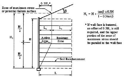
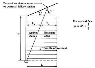
- Establish the vertical spacing of the reinforcement
- The vertical spacing of reinforcement should not be more than
- 800mm for precast concrete panel
- 400mm for Geosynthetic wrapped face
- 2 times block depth or 810mm whichever is less for MBW
Reinforcement Resistance Check
If the factored tensile force acting on the reinforcement is less than the factored tensile resistance of reinforcement then structure is safe.
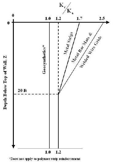
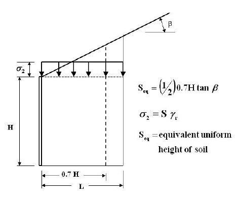
Tensile stress at certain depth is calculated as:

Here Kr/Ka is the coefficient of lateral stress ratio and Seq is the equivalent depth of the soil above the reinforced fill, shown in figures:
Maximum tensile force at the reinforcement present at certain depth:

Here Rc is the coverage ratio, defined as the Ratio of width of reinforcement to the number of reinforcement provided.
The tensile resistance of the reinforcement:

Here installation, creep & durability are taken as reduction factor for long term durability of reinforcement.
The resistance factor (ɸ) is applied on the allowable stress in reinforcement, taken as:
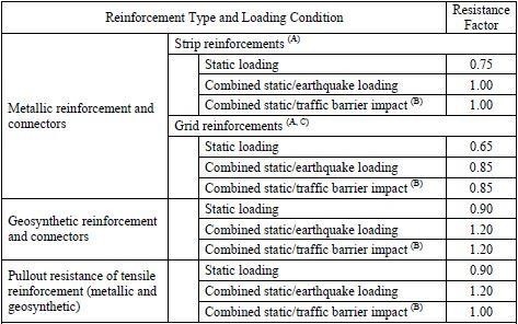
Resistance to pull out
Pull out resistance of reinforcement is Calculated as:

Here vertical stress is calculated as shown in figure:

Minimum embedment depth in resistance zone is 1m.
Structural resistance of connection
- The connection should be tested for the maximum tensile force generated in the reinforcement.
- Test should be carried out in the laboratory for connection strength.
Structural resistance of facing material
- The facing material should reinforce for the shrinkage and temperature steel.
- Arrangement should be done according to the reinforcement placement.
Service Limit State
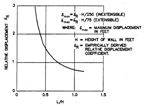
Lateral Movement
Lateral movement of wall should be calculated as:
Vertical Movement
The vertical movement or settlement of wall should be under limit:
- 1/500 for Full height panels
- 1/200 for MBW
- 1/50 for welded wire mesh
Global and Compound Stability
- The global and compound stability of the wall should be 1.3 to 1.5.
- When the slip surface passes through the reinforcement, compound stability is obtained.
- If the failure surface is away from the reinforced zone, global stability is obtained.
- Design the drainage system.
Reinforced Soil Slopes
Reinforced soil walls are very flexible when compared to conventional gravity structures and can be adapted to suit a wide range of conditions and is the most cost effective solution to retaining walls. Reinforced soil slopes can also provide effective resistance to differential settlement and seismic activity and eliminate surficial stability issues. And their flexibility makes them applicable in a broad range of project types.
Form of reinforced soil that incorporates planar reinforcing elements in constructed earth slope structure with face inclination of less than 700.
Basic material needed is:
- Granular Earth fill
- Reinforcement
Pros and Cons of MSE walls
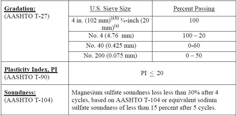
Reinforced Material Properties
Facing System
Based on the erosion control and other factors, facing is divided into:
1.Vegetated Facing

2. Hard or Armored Facing

Failure Models of RSS

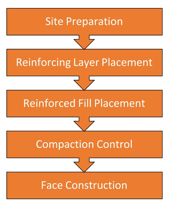
Construction Sequence
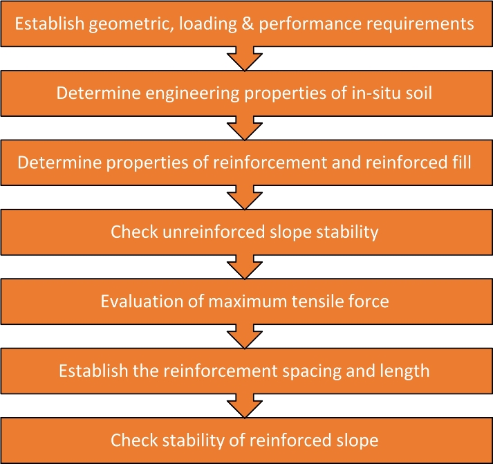
Design Sequence
Maximum Tensile Force
The maximum tensile force can be evaluated as:

Tensile force is found for the most critical surface defined as the surface requiring the greatest amount of reinforcement strength.
Compare the maximum tensile force (Ts) value with the value obtained from the graph, should be in limit of 25%:

Reinforcement Length
For the obtained tensile force, calculate the reinforcement length using:

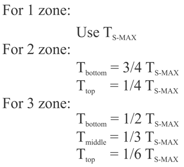
Uniform distribution of reinforcement is suitable up to height of 6m. For heights > 6m, slope is divided into zones and tensile force is distributed as shown in figure:
Stability Checks
External stability checks including deep seated failure should be carried out using software.
Local bearing failure should be analysed if soft soil is present beneath the structure, evaluated as:

Settlement and seismic stability check should be carried out.
Design the drainage system.
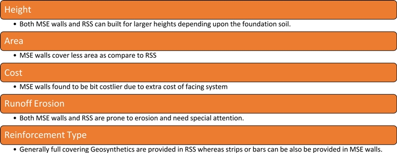
Comparision between MSEW & RSS
Authored By:
Aman Middha, Geotech Engineer at HMBS Textiles Pvt. Ltd
Shubham Gupta, Geotech Engineer at HMBS Textiles Pvt. Ltd

