
In this paper, a methodology for carrying out dynamic analysis of pile-raft foundation for site-specific earthquake has been demonstrated with an example of pile-raft foundation of Custom office tower at Kandla port. Pile-raft foundation at Kandla port had tilted due to lateral spreading under liquefaction during January 26, 2001 Bhuj earthquake. Limited studies on this pile-raft are reported in literature, however, no study for site-specific earthquake with numerical simulation of soil is reported in literature. In the present study rock level ground motions for site-specific scenario earthquake of Mw 7.6 with seismological parameters of Bhuj earthquake 2001 are generated using extended finite source stochastic models. Surface level ground motions are obtained through one dimensional equivalent linear wave propagation analysis. Two dimensional numerical modelling of pile-raft foundation and the sub-soil interactions are done using finite element program PLAXIS 2D and the dynamic analyses are carried out for rock level and surface level ground motions. Settlement of pile-raft and response of soil at different depths in terms of settlement, lateral displacement, excess pore pressure and acceleration are studied for rock and surface level ground motion. To account for the gentle ground slope reported to be existing at site, dynamic analyses are carried out for horizontal ground slopes of one degree and five degree in addition to flat ground case and lateral spreading and settlement of soil observed from analyses are compared with field observations reported during the Bhuj earthquake.
INTRODUCTION
Studies on Pile-raft of Kandla port with equivalent static loads for serviceability and seismic conditions are reported in literature by modeling the soil-structure interaction effects by elastic springs [5]. In the present study dynamic analyses of typical sections of pile-raft foundation of customs office tower at Kandla port assumed to be situated on flat ground and ground with horizontal slope of one degree and five degree are carried out using computer program Plaxis 2D for site-specific scenario earthquakes. Due to the non-availability of information on bedrock depth at Kandla port site, in the present study site-specific ground motion of Mw 7.6 is generated for hard rock site class with seismological parameters [7] of Bhuj 2001 earthquake using extended finite source stochastic models for the latitude and longitude of Kandla port. Surface level ground motions are obtained through one dimensional equivalent linear wave propagation analysis through the 40 m soil overburden.
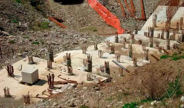
The 22m high six-floor custom office tower building at Kandla is located on the pile-raft foundation of size 11.45mx11.9mx0.5m supported by 32 piles of 0.4m diameter. Each pile is of length 18m and embedded into 40m depth of soil. Subsoil consists of soft clayey soil of 10m depth, sandy soil of 12m depth, brown hard clayey soil of 10m depth and clayey sand of 8m depth. Two dimensional numerical modeling of typical section of pile-raft with the soil mesh of 151.45 m in the horizontal direction and 40 m in the vertical direction is done and time history dynamic analysis are carried out with rock and surface ground motions. In order to account for the gentle ground slope reported to be existing at site, three slopes of ground viz., 0 degree, 1 degree and 5 degrees are considered for the analysis which are designated as case 1, case 2 and case 3 hereafter. Through the time history dynamic analysis, settlement of pile-raft and response of soil at different depths in terms of settlement, lateral displacement, excess pore pressure and acceleration are obtained for rock and surface level ground motion and the comparisons are made with the field observed values reported in literature for all the three cases.
METHODOLOGY
Methodology for carrying out dynamic analysis of pile-raft foundation involves the steps of generation of site-specific ground motion, numerical modeling of soil and numerical modeling of pile raft as detailed below:
Generation of site-specific ground motion
Due to the scarcity of recorded ground motions, generation of site-specific artificial strong motions using stochastic models by identifying major fault zones and propagating seismic waves generated at these potential sources to the sites of interest is well accepted in literature [8-10]. In this process, path effects and anelastic attenuation effects predicted by the empirical and theoretical models [10] are used. For source representation, point source models [11] or finite source models [12] are widely used. In this paper, artificial ground motions are generated for Mw 7.6 earthquake with parameters [7] of Bhuj earthquake using extended finite source stochastic model (EXSIM) proposed by Motazodian and Atkinson [13]. Peak ground acceleration (PGA) of ground motion simulated in the present study for rock level is 0.49g which is in close agreement with Amax value reported for main shock of Mw 7.6 for stress drop of 200 bars by Singh et al. [7]. One dimensional equivalent linear ground response analysis has been carried out for the Kandla port site with the available information on soil overburden for a depth of 40 m (Fig.1) using computer program SHAKE2000 [14]. The PGA of surface level ground motion obtained for present study is 0.187g. However, the surface level peak ground motion reported in literature for Kandla port by Dash et al., [5] is 0.33g. This deviation may be due to the non-availability of information about soil layers below 40 m, hence, surface level ground motion obtained through wave propagation in the present study is scaled to PGA of 0.33g and adopted for dynamic analysis of pile-raft foundation.
Numerical modelling of soil for pile-raft analysis
The plain strain model of pile-raft foundation has been created with soil mesh of 151.45mx40m and the water table is located at 1.5m from the ground level as per the borelog details available in literature [4]. The boundaries of the model are taken sufficiently far away to avoid direct influence of the boundary conditions. The earthquake vibrations are induced by imposing a prescribed displacement at the bottom boundary. The vertical component of the prescribed displacement is kept zero. At the far vertical boundaries, absorbent boundary conditions are applied to absorb the increments of stresses on the boundaries caused by dynamic loading. Horizontal fixities (ux=0) are applied at vertical boundary and both horizontal and vertical fixities are applied at bottom boundary (ux=0, uy=0). For cases 2 and 3 the entire soil profile and pile-raft system are modelled with inclinations of one degree and five degrees respectively with horizontal and the ground motion is applied at the bottom of the model.
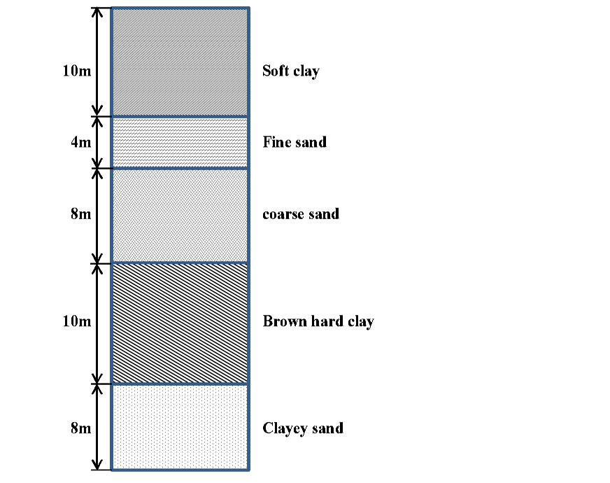
The clay layers are modelled with Mohr Coulomb (MC) constitutive relation and sand layers are modelled with hardening soil (HS) constitutive relation [15]. Yield surface of hardening soil model and Mohr coulomb model are given in Fig. 2.
Numerical modelling of pile-raft
The front view of six-floor customs office tower building is shown in Fig. 3a. Dimensions of raft slab, columns and pile are given in Fig. 3b. The typical section of pile-raft foundation which supports 12 columns of the building has a cut out for 7.7mx4.7m as shown in Fig.3c. As it is reported by Dash et al., [5] left and middle columns are of size 0.25mx0.25 and right columns are of size 0.45mx0.45m the entire pile raft system consists of 32 nos. of piles and each pile is 18m long with diameter of 0.4m. In an earlier study, three dimensional modelling of pile-raft with all the 32 piles has been carried out by authors for static loads and the axial force, bending moment and settlement variations of pile-raft and individual piles were studied [6]. In the present study, dynamic analysis has been carried out for a typical section of pile-raft of dimension 11.45mx0.5m raft with three equivalent piles representing the rigidity of pile groups in the front row as shown in Fig. 3c using Plaxis 2D Plain strain model. During analysis, axial loads from superstructure are assumed to be acting on top of each pile group (equivalent pile) as shown in Fig. 3c in addition to earthquake load which is applied at 40 m level. Settlement response of pile-raft has been observed for rock and surface level ground motions and the comparisons are made with values reported in literature.
RESPONSE OF PILE-RAFT FOUNDATION
Settlements of pile-raft at different points along the length of the raft, are observed from dynamic analyses for rock and surface ground motions. The settlements and lateral displacements at left edge and right edge for raft and pile tip for rock and surface level ground motions are given in Table 1. From the results it is seen that right edge settlements are more for all the cases compared to left edge settlements. The percentage differences in settlements between right edge and left edge are greater for surface ground motion than that of rock ground motion. The percentage differences between right edge and left edge for case 1 and case 2 are similar even though the absolute settlements are more for case 2 than that of case 1. The right edge settlement for case 3 is in the order of 98% and 190% more than that of left edge settlement for rock and surface ground motions respectively. Tilting of pile raft by 1.5 degrees and 2.92 degrees is observed for RGM and SGM respectively for case 3.


RESPONSE OF SOIL
As mentioned in the sections above, dynamic response of soil is observed for three different cases viz., Case 1, Case 2 and Case 3. The deformed shape for the three cases for rock ground motion (RGM) and surface level ground motions (SGM) are shown in Fig. 4a-f. As it can be seen in Fig. 4, responses of soil is different at different sections along the length considered for numerical study. Other responses of soil viz., settlement, lateral displacement, excess pore pressure and acceleration are observed typically along a vertical section next to the right edge of the raft foundation indicated as a line in Fig. 4.

Settlement
Settlement time histories at different levels for rock ground motion and surface ground motion are shown in Fig 5 (a)-(f) for the three cases considered. Static load from superstructure is applied at the top of raft along with earthquake excitation. Peak values of settlement after the earthquake shaking are given in Table 2. The percentage difference in peak settlement at surface level for case 2 and case 3 with respect to case 1 are 10.5% , 452.6% for rock ground motion and 7.3%, 493.9% for surface ground motion respectively.
Lateral displacement
Lateral displacement time histories at different levels for rock and surface ground motions are given in Fig. 6 (a)-(f) for the three cases considered. It is seen that for surface ground motions peak values of lateral displacement are high and variation along the height is less. This indicates that the entire strata experiences the lateral displacement of similar order for case 1 and case 2. Peak lateral displacement for surface ground motion are observed to be higher compared to peak lateral displacement observed for rock ground motion. The percentage difference in peak lateral displacement at surface level for case 2 and case 3 with respect to case 1 are 8.7%, 212.8% for rock ground motion and 17.9%, 35.5% for surface ground motion respectively.
Excess Pore pressure
Excess pore pressure time histories at different levelsfor rock and surface ground motions are given in Fig. 7 (a)-(f) for the three cases considered. Excess pore pressure ratios (EPP) are obtained and it is observed that for case 3 at the level of 10 m where, fine sand is located below the clay layer, the EPP values are more than 1 for both RGM and SGM which indicates the occurrence of phenomenon of liquefaction.
Peak ground acceleration
Acceleration time histories at different levelsfor rock and surface ground motions are given in Fig. 8 (a)-(f) for the three cases considered. Peak ground accelerations observed at 10 m level are found to be higher for rock ground motion compared to other layers for all the three cases considered.


CONCLUSIONS
In the present study a methodology has been demonstrated for carrying out dynamic analysis of pile raft foundation for site-specific earthquake. The methodology has been demonstrated for the pile-raft foundation of Custom office tower at Kandla port which had tilted due to lateral spreading under liquefaction during January 26, 2001 Bhuj earthquake of moment magnitude 7.7. In the present study numerical modelling of pile-raft foundation and the sub-soil interactions are done using two dimensional finite element program PLAXIS 2D. Dynamic analysis are done for the three cases viz., pile-raft in level ground, one degree slope ground and five degree slope ground for rock level ground motion and surface level ground motion. Responses of raft, pile and soil are observed. The settlement of pile reported in literature from analytical study is 35 cm and reported from field survey is 45 cm. From the present study settlement for case 3, at left and right edge of raft are observed to be 31 and 61 cm respectively for rock ground motion and 31 and 90 cm settlement for surface ground motions. Settlement of pile tips of left and right edge piles are observed to be 34 cm and 60 cm for rock ground motions and 37 cm and 87 cm settlement for surface ground motions respectively. Tilting of pile raft by 1.5 degrees and 2.92 degrees is observed for rock ground motion and surface ground motion respectively for the five degree ground slope model in the present study. It is reported that lateral spreading of soil of the order of 80 cm to 100 cm was observed from reconnaissance survey immediately after earthquake and lateral spreading of 83 to 91 cm has been reported from analytical studies. In the present study lateral displacement of raft is observed to be 49.4 cm for rock ground motion and 82 cm for surface ground motion. Lateral displacement of top most layer for the section chosen near the right edge of the raft for case 3 is 60.7 cm for the rock ground motion and 89.7 cm for the surface ground motion. Hence simulations for case 3 are in closer agreement with the values reported in literature from analytical studies and damage surveys for pile settlement and lateral displacement. Further it is reported in literature that, sand layer at 10 m depth at Kandla port got liquefied during Bhuj 2001 earthquake. In the present study, excess pore pressure ratio for case 3 at 10 m level is observed to be more than 1 for both rock ground motion as well as surface ground motion indicating the phenomenon of occurrence of liquefaction which is in agreement with literature.
From the studies made, it is seen that results of the dynamic analysis for site-specific earthquake for pile raft foundation of Custom tower building at Kandla port situated in gentle sloping ground of about 5 degrees are in closer agreement with the field observed values and analytical study results reported in literature. The methodology proposed in this paper can be adopted for predicting the settlement and lateral spreading of foundation and soil for future earthquakes.
References
- Sheth.A, Jain.K.S, Thiruppugazh.V,“Earthquake capacity building and risk reduction measures in Gujarat
- Pankaj Agarwal S.K. Thakkar and R.N. Dubey “Behaviour of building, bridges, dams and ports during Bhuj earthquake of january ISET Golden Jubilee Symposium, IIT Roorkee.
- B.K. Rastogi, “Ground deformation study of Mw
- Dash, S. R., Govindaraju, L. and Bhattacharya, S.. “On the probable cause of the failure of kandla port and customs office tower
- Dash, S. R., Govindaraju, L. and Bhattacharya, S. “A Case Study of Damages of the Kandla Port Tower Supported on a Mat-Pile Foundation in Liquefied Soils
- Buvaneswari, C., Kamatchi, P., Syed Masoodhu, S, “3D numerical static analysis of pile-raft foundation of customs office tower at Kandla port for service load” Proceedings of fourth national conference on recent advancements in Geotechnical engineering, April, 17, Government College of Technology, Coimbatore pp 169-174.
- Singh, S. K., Bansal, B. K., Bhattacharya, S. N., Pacheco, J. F., Dattatrayam, R. S.,Ordaz, M., Suresh, G. and Hough, S. E. “Estimation of ground motion for Bhuj (26,January 2001; Mw 7.6) and for future earthquakes in India” Bulletin of Seismological Society of America, 93, 353-370.
- Boore, D. M. “Stochastic simulation of high frequency ground motions based on seismological models of the radiated spectra”
- Boore, D. M “Simulation of ground motion using the stochastic method” Pure App. Geophy., 160(3-4), 635-676.
- Beresnev, I.A., Atkinson, G.M. “Source parameters of earthquakes in eastern and western north America based on finite fault modeling”
- Boore, D.M., Atkinson, G.M. “Stochastic prediction of ground motion and spectral response at hard-rock sites in Eastern North America” Bull. Seism. Soc. Am., 77(2), 440-467.
- Hartzell, S. H. “Earthquake aftershocks as Green’s functions.” Geophy. Res. Lett.,
- Motazedian, D., Atkinson, G.M. “Stochastic Finite-Fault Modeling Based on a Dynamic Corner Frequency”, Bull. Seism. Soc. Am., 95(3) 995-1010.
- Ordonez, G.A.“SHAKE : A computer program for the I-D analysis of geotechnical earthquake engineering problems user’s manual”, University of California, USA.
- [15] Brinkgreve, R.B.J., Broere, W. and Waterman D “Plaxis 2D version 8”, Delft University of Technology & PLAXIS
About the author
Palaniyandi Kamatchi is a Principal Scientist at CSIR Structural Engineering Research Centre. The author has been working as a Principal Scientist at CSIR Structural Engineering Research Centre for more than 25 years. She specialises in Seismology and Earthquake Engineering.