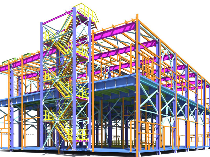
The workflow of steel often causes a lack of information, and the high cost, reduced efficiency in the various stages of the project. BIM technology simulates building by digital real information, sharing the information by central document, that close connection with the various stages of the process, and exchange information, to improve efficiency and reduce costs. Fabrication-specific software is growing, streamlining processes using BIM information and allowing optimized schedules in steel construction. Given below are few applications of BIM technology used for steel structure design.
Application of BIM Technology in Steel Structure Design
BIM creates efficiency and users will get several benefits. You will realize some of the greatest value of BIM through its potential to cut down on rework, such as re-keying information into models or making changes in the field. Some of its application in steel structure design is given below.
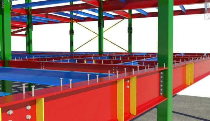
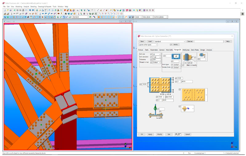
Joint detailing in steel – For modeling processes of some software, the connecting detail of structures joints defaults which means that the connecting detail is invisible. But provide convenient and humanized support for Joints Design. Besides, it also supports the Manual Input Joints Parameters and Intelligentized Generation Joints Parameters which make the Model Building Approach more convenient. After the date reading, automatic checking can calculate the subsequent installation issues of construction in advance. The detailed building of the 3D Model will ensure the subsequent duration analysis and detailed design. It is more convenient for the process of modeling by generating intelligent joint parameters. After reading the data, automatic checking of joints can predict installed problems that may occur in the future of the construction process.
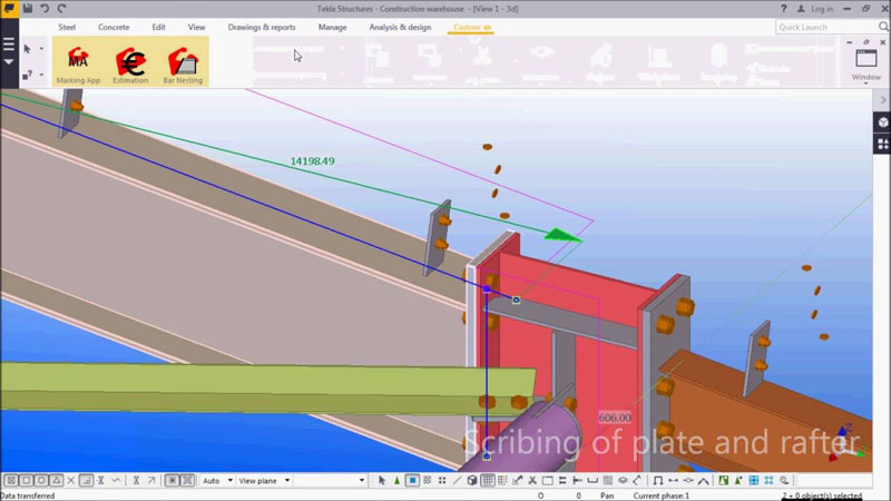
Developing a scribing interface in steel projects – BIM interface saves all the laborious workshop ‘marking out’ time, which in principle is no different from the way that the outline of a stamp is placed on envelopes to indicate their intended position. Welders can then simply weld the fittings in the correct location with all the reference information and weld requirements on the member rather than referring to the fabrication drawings, eliminating another interface for error. All the 3D geometry is transferred to their software systems allowing all holes, copes, member bevels and weld preparation information to be transferred, as all of this information can be far too complex and is not totally supported by the current industry DSTV4 (Deutscher STahlbau-Verband) manufacturing format. Shortly this kind of technology will control welding robots and reinforcement placement robots for the precast concrete sector.
BIM tools to manage steel structure life cycle – The lifecycle of a steel building project, from design through inception and facility management, comprises multiple project management processes where data and information are defined and generated. To support processes throughout the project lifecycle, there needs to be a method of structuring and storing information that takes into account information needs at later project processes. The benefit of a structured information system based upon process information needs is explored as to how it can enhance the use of information within a BIM to support lifecycle processes. The use of Building Information Models (BIMs) conceptualizes lifecycle management principles with the use of information-rich digital models to exchange information between parties in support of the lifecycle of a project.
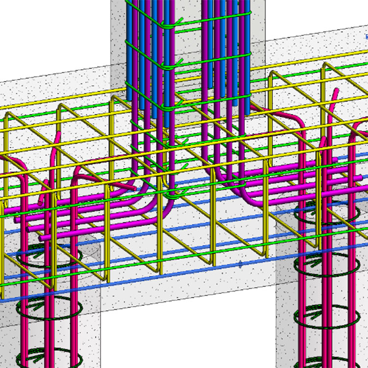
Steel rebar Information fragmentation – If we have the information classification system, then it could be integrated into the database framework of the BIM applications to support user input of information for each project. Steel rebar is calculated and stored for making decisions through the estimate, schedule, and procurement processes. Steel rebar is usually quantified as total tonnage for an estimate. The objective of the estimate process is to calculate a total quantity of steel that can then be multiplied by a unit cost to estimate a total cost. The format in which the steel quantity is generated is therefore not adequate for subsequent processes such as scheduling. To support the scheduling process for calculating durations, the quantity information needs to be partially regenerated to correspond to nine separate construction activities that match the nine wall assembly sections used for planning the construction work. The new quantities are needed to calculate activity durations by dividing the tonnage of steel in each section by crew production rates (tons/day). Similarly, for the procurement process, quantities need to be organized by bar size to allow for ordering, tracking, and delivering material.
Work Task Information Framework for steel construction – Work Task Information Framework (WTIF) is proposed to integrate workflow/work tasks with geometric assemblies and various information categories. The assembly classification consists of three levels: Assembly (e.g. Foundations), Sub-Assembly (e.g. Footings and Foundation), and Construction Types (e.g. Cast-in-Place Concrete Walls). The information categories for each Construction Type are the same, though the information they store may vary. Work Tasks and Means & Methods help define the items of information in each category and the structure of sub-categories. The Material Take-off, Estimate, Resources, Schedule, and Material Procurement categories organize information based upon the Work Tasks that are associated with the construction type classification.
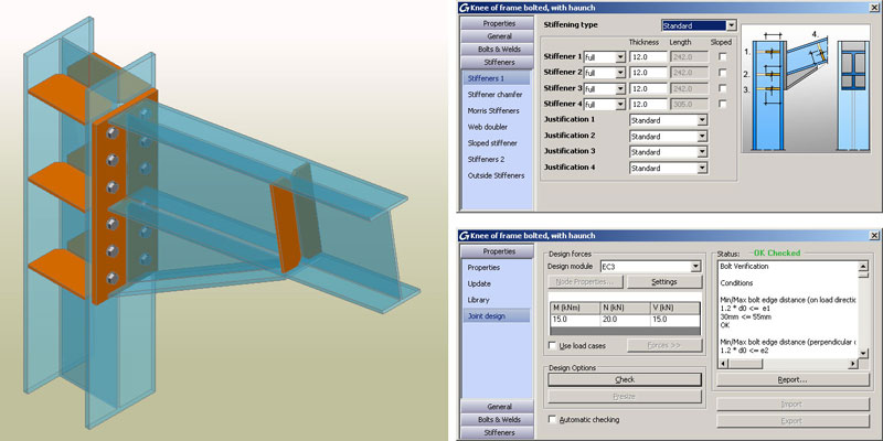
Calculation analysis and collision check of steel joints – BIM analyzes the internal force of members, system architectures and integral stability of steel structures. The calculation and the analysis are mainly to determine whether the joint meets the requirement of loading and construction conditions, so it has very practical applications. Collision check needs to be specific to joints, the object of inspection includes the place between different bolts at the joint, the place between bolts and flanges. Besides, easy installation and the collision check of large members are also necessary. By the collision checking in the phase of the design model, the design defects and the potential troubles can be solved previously, and issues can be controlled successfully in advance.
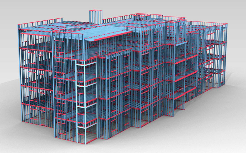
BIM into Cold-formed Steel Residential Buildings – Cold-formed steel construction (CFS) has proven to be a worthy alternative to traditional building systems due to its high strength to weight ratio, a high degree of dimensional exactness and sustainability. The information integration provided by Building Information Modelling (BIM) can be utilized to enhance the efficiency of this construction system. Programming tools specific to CFS residential buildings can be utilized during the different project phases to facilitate BIM implementation. During the planning phase, complex floor plan arrangements are easily created from a few simple modules similar to modular construction. During the design phase, the building model is created from parametric CFS objects of walls, floors, and bracings. Structural optimization tools related to member and system optimization are also employed during the design stage. Once the building model has been created using these tools, it can be used efficiently to explore and evaluate the project’s constructability before it is built, produce workshop drawings, visualize construction processes through 4D simulation and clash detection in addition to the required data for Numerical Control Machine fabrication.
Conclusion
BIM implementation within steel structural engineering methodology clearly and objectively shows how to carry out implementation and includes processes for analysis and diagnosis, a rethinking of objectives, identification of requirements, planning, and monitoring of the proposal.
Image Source: revitstructureblog.files.wordpress.com, construsteel.com, csengineermag.com, blogs.autodesk.com, mdpi.com, graitec.com, vertexcad.com, lynda.com