Structural audit & non-destructive testing is a niche field in civil engineering which helps practicing civil engineers to arrive at technically correct solutions for structures in question. It is a health monitoring system devised to check current status of a building/structure for its requirements of health improvement measures in terms of repairs / restoration / rehabilitation / adaptive re-use.
Structural audit becomes necessary for following reasons.
- M.C.G.M. directive to get structural audit done to buildings older than 30 years at every 3 years & buildings older than 15 years at every 5 years. Most of the time, there is no such data available for heritage structures unless it goes for major revamp/conservation
- Leakages / structural cracks in buildings handed over recently / few years back
- Dispute reprisals between contractor & client/architect Quality assurance
Beyond such compulsions, following could be reasons to opt for structural audits & N.D.T.
- Buildings observed having cracks or leakages which are indicative of its health hazard, thus calling for an inspection through an expert agency. This may happen even to buildings that are newly constructed, a few months /years back.
- When a dispute arises between client & contractor & /or architect/consultant, Structural audit & N.D.T. comes handy to resolve & arrive at a logical conclusion
- Clients who are quality conscious seldom get Structural audit & N.D.T. done to ensure quality at site post construction instead of solely relying on cube results of a laboratory.
- Results could vary but the necessity of Str. Audit & N.D.T. remains the undisputed need of the construction industry.
- N.D. TESTS ARE PATHOLOGICAL TESTS PERFORMED AT CLINIC & AT LAB TO ENABLE DOCTOR WITH DATA FOR CORRECT & PRECISE DIAGNOSIS
- BUILDINGS/STRUCTURES ARE LIKE HUMAN BODIES & BEHAVE IN LIKEWISE MANNER
- AUDIT RESULTS CAN DRAW A PRESCRIPTION FOR VED WORKS FOR ENHANCED STRUCTURAL STABILITY
Advantages of structural audit for the analysis of Structural audit & NDT for modern & heritage buildings are as follows
- To ascertain cause & extent of deterioration, of materials failure in heritage structures
- In forensic engineering analysis to determine causes of structural failure
- In insurance business, to ascertain/ predict remaining life expectancy of structures
- In Banking, to check of valuation at given period

Following are the structural audit components & tests
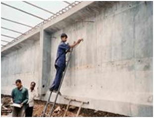
- Visual Inspection- to check symptoms of reasons/causes of health deficiencies of a building’s structure like leakages/seepage, cracks, delimitation, distress, separation etc.
- Nondestructive testing- Tapping using nylon hammer, Rebound hammer test for surface hardness, Ultrasonic Pulse velocity for concrete compressive strength & general quality, Half-cell potential meter for corrosion testing of steel, digital moisture meter for leak detection etc.
- Profometer test for rebar location, its diameter & concrete cover depth checking
- Concrete / stone digital microscope to check particle distribution & fissures/ foreign particle presence in specimen under testing
- Corrosion monitoring equipments for long term inspection, mainly used for marine structures
FOLLOWING tests are performed on metal structures for analysis of Structural audit & NDT for modern & heritage buildings(like P.E.B., structural steel used in industrial, composite or heritage structures.)
- Magnetic particle induction test for structural steel crack detection
- Digital Elcometer for coating thickness on ferrous & non-ferrous metal surfaces
- Digital metal hardness test for ferrous & nonferrous metals & its alloys
- Additionally, there is testing of soil to check FOR ITS SBC BEARING CAPACITY, PERMEABILITY & STRATA LAYER, CBR (California bearing ratio), PLATE LOAD TEST, SOIL RESISTIVITY TEST
- PILE LOAD TEST (STATIC & DYNAMIC) & PILE INTEGRITY TEST
- PULL OUT STRENGTH CHECKING OF CONCRETE & REBARS
- DRONE SURVEY
- LIDAR TEST (Light detection & Ranging) active remote sensing sensors to measure distance of an object & form virtual image by using laser beam
- G.P.R. TEST for buried cables, antuques etc.
- MATERIAL TESTING OF CEMENT, SAND, LIME, EPOXY, PU ETC.
- CEMENT AGGREGATE RATIO & CHEMICAL ANALYSIS OF CONCRETE
Following is the description of various test equipments
REBOUND HAMMER:
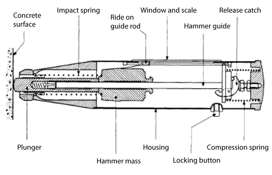
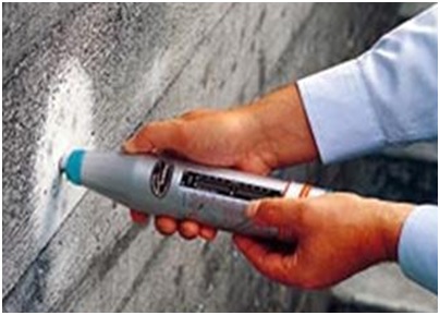
It is used to check surface strength/Soundness of cover concrete Which in turn can be converted to indicative compressive strength of concrete. It is also called Schmidt hammer test that consists of spring controlled metallic equipment that slides on a plunger within tubular housing. Plunger is pressed against the concrete surface so the spring-controlled mass bounces back. Extent of rebound is a measure of surface hardness which is indicated on graduated scale. The result thus achieved is called rebound number/rebound index. Concrete having lower strength will have lower stiffness & thus will absorb more energy to result in yielding lower rebound number.
As per IS 13311 -1992 Part 2, objective of rebound hammer test are as follows.
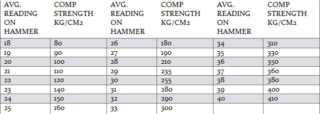
- To determine comp. strength of concrete by relating rebound number to it as per manufacturer’s data/table.
- To assess uniformity of concrete.
- Quality assessment of concrete in comparison with its design standards/specification laid.
- Comparison in relative terms for one concrete member to another & with respect to concrete
- cube strength to check defects ( if any) in concrete ingredients or its laying, compaction, form work etc. in their acceptable & questionable parts of concrete.
- Reading up to 17 means compressive strength of concrete @ less than 80 kg/sq. cm.
Rebound hammer is supplementary test & can not be relied up on fully as STAND-ALONE test. Following are its limitations.
- Only surface concrete strength indication. Do not cover core concrete
- Surface needs to be smooth or else results show serious variations
- Results of concrete having cracks/undulations or aggregates on surface are not reliable
- results on low strength concrete at early age show poor results
- Results relate to stiffness of concrete than strength
- Rebound numbers are high on wet concrete specimen than dry ones
- High alumina cement type 3 show 100% higher strength than type 1 cements
- Super sulphate cements type 2 show 50% lower strength
- Large aggregate or rebar near surface show higher results while concrete having honeycomb or bleeding or voids show lower results
- Rebound hammer placed near edges of column/ beam or staircase bottom slab show lower results than actual
- Position of holding hammer & force applied by different individuals may show different results than actual strength
- Relationship of rebound hammer test results relating to comp. Strength are only empirical & not theoretical
- Regular calibration only can give reliable results
- No relation shall be derived based on average strength of concrete v/s designed strength
- Remarkably high variation of strength of one/few structural members should lead to carbonation test of concrete which makes concrete excessively hard & brittle
- This test should be used in conjunction with other NDT methods instead of stand-alone test & that too with proper understanding of site situations
- Available in mechanical & digital versions
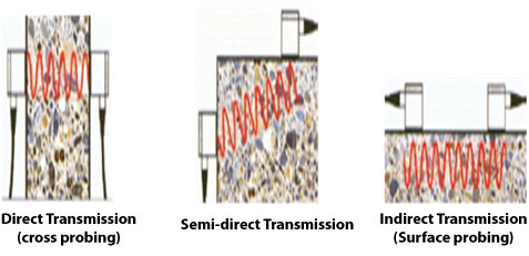
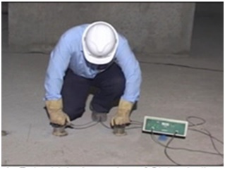
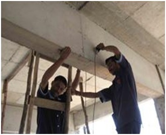
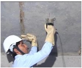
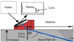
Ultrasonic Pulse velocity results ASTM C597
- As per IS 13311-1992 Part 1 /IS 516 Section 1 part 5-2018, UPV is in situ test to check quality of concrete & natural rock/stones by passing a ultrasonic sound wave & checking its velocity. It indicates homogeneity of concrete/stone, evaluates dynamic modulus of elasticity, estimates depth of cracks, honeycombs & can be used to check effectiveness of repairs. This is an indicative test & it is recommended to conduct other tests like core cutting to correlate results of data generated through UPV test results.
- Pulse velocity above 4.5 Km/Sec. – Excellent Concrete
- Pulse velocity between 3.5 to 4.5 Km/Sec. – Good quality Concrete
- Pulse velocity between 3 to 3.5 Km/Sec. – Medium/doubtful quality Concrete
- Pulse velocity between 2 to 3 Km/Sec. – Poor quality Concrete
- Pulse velocity below 2 Km/Sec. – Unacceptably poor-quality Concrete
STANDARD DEVIATIONS IN ULTRASONIC PULSE VELOCITY TEST
- 25% in the case of U.P.V. results as per IS 13311 Part-2-1992
- Characteristic strength FCK= Mean target strength FCM ( Average strength of concrete cubes tested after 28 days of curing)* standard deviation for respective grade of concrete as per IS 456-2000. Results beyond 5% should not fall below FCK
- Diff. in requirement of structural grade concrete of IS 456 -1978 & its revision in year 2000 should be considered while giving judgment based on UPV results also while considering age of structure, importance of structure & structural member in question, purpose of testing e.g. for forensic, general purpose quality assurance, dispute resolution & so on.
ULTRASONIC ECHO METHOD/ TOMOGRAPHY OF CONCRETE/STONE MATERIALS:
- Frequency used for concrete 500 Hz as max. & 20 Hz as minimum
- UPV Need access on both side of concrete member to get reliable information while Echo system is one dimensional
- Stress wave reflected from inherent defects such as crack or void is determined
- Initially developed for metals, now applicable on thin walls/slabs
- Low frequencies are used in case of concrete
- IMPACT ECHO method ASTM C1383 is also used
COMPARISON OF IMPACT ECHO TO UPV METHOD:
- Impact echo does not have need of heavy transmitter & receiver
- However, impact echo does not have directionality like UPV as IE energy propagates in all directions so reflections are received from all directions. Exact location finding is thus difficult
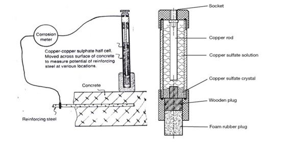
HALF CELL POTENTIAL TEST FOR REBAR CORROSION:
- ASTM C 876 where steel bar is one electrode & Cu SO4 IS ANOTHER electrolyte (Concrete). This method detect negative charge in reinforcement causing likelihood of corrosion possibility which is measured using half cell
- At Anode~Ferrus becomes ferric while at cathode, Water + oxygen converts into 4OH.
HOW HALF CELL POTENTIAL WORKS:
- If bar corroding electrons flow from bar to cell.
- At half-cell electrons transform cu2+ ions in the cuso4 solution to cu atoms and deposit on the rod in the half cell.
- Voltmeter then indicates a negative value.
- The more negative the value, the higher is the likelihood of corrosion.
- There is no current in the circuit.
HALF CELL POTENTIAL TEST RESULTS:
- Test results evaluation is:
- 0 to 150 mv- not corroded
- 150-300 mv- partially corroded
- 300-600 mv- corroded
- 600-900 mv heavily corroded concrete/ discontinued reinforcement
- Not useful for epoxy coated/ fusion bonded bars
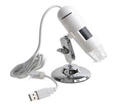
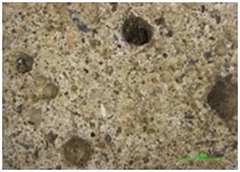
DIGITAL CONCRETE MICROSCOPE:
- Useful in understanding concrete density, particle size distribution, inherent cracks/honeycombs & fine to coarse aggregate ratio while inspecting concrete after core cutting

- Newer versions are available where cameras can be inserted in concrete by drilling holes.
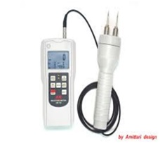
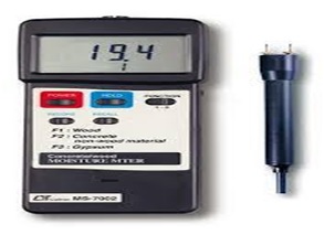
MOISTURE METER TESTING:
- Available in digital version with metal probe showing result in % for concrete & wood
- Useful to detect leakage location having highest % moisture. This avoids unnecessary speculations & breaking.
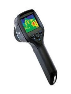
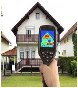
DIGITAL THERMAL IMAGING TEST:
There is an advance test than moisture meter test which demonstrate leakages in more accurate manner depending on thermal conductivity of different building materials used in construction.
- Takes photographs of building & shows them in different colors depending on temperature/ conductivity of various building materials.
- Moist areas have remarkably high humidity thus source of leaks is shown in diff. color, identifying exact location
- Need an expert to judge location based on pictures
- Site visit of person inspecting pictures/ images add value to precision of judgment
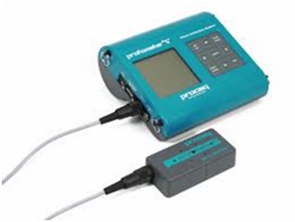
PROFOMETER TESTING:
- Imported from Switzerland to check diameter & spacing of embedded reinforcement & depth of cover concrete
- It has memory storage & printing facility to avoid remembering results or manipulation
- Useful in structural diagnostics
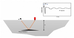
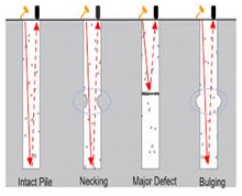
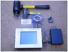
PILE INTEGRITY / SONIC ECHO TEST:
- Impact is made on the pile/ raft foundation top to generate stress waves which travel through height of str. Member & return to transducer/ accelerometer coupled on head of foundation under testing where time taken is measured
- Time of impact generation & vertical movement of pile/raft concrete due to impact are recorded by digital data acquisition devices like oscilloscopes periodically.
- Results will tell story of discontinuity/integrity of foundation
STRESS WAVE METHOD OF TESTING OF CONCRETE
- Impact is given on concrete member to create stress & stress wave travels through concrete as medium as sound wave travel through air analogy
- Speed of stress wave propagation is function of modulus of elasticity, Poisson’s ratio, density & geometry/shape of concrete member
- Waves generated are dilatational P waves, distortional S waves & Rayleigh/Surface R waves depending on characteristics of the source.
- This can indicate anomalies in concrete
SPECTRAL ANALYSIS & SURFACE WAVES SYSTEM & SEISMIC REFLECTIONS:
- Developed between 1960 & 1970, then research was dormant till 1980 which was again taken up at University of Texas Austin
- Method is used to determine stiffness profile of soil, asphalt or concrete pavements besides concrete str. Members & also for checking changes in elastic properties of concrete during curing, detection of voids & internal damages
PRINCIPLES OF SASW:
- An impact is used to generate R wave/ surface wave & 2 receivers are used to monitor its motion, Signals are processed & calculated as per mfrs. Scheme are used to ascertain stiffness of layer under testing
- Like Impact echo, R waves also contain range of components of diff frequencies/ wavelengths
ADVANTAGES OF SASW METHOD:
| Ultrasonic through directs transmission (pulse velocity) | Portable equipments is available relatively carry to time |
| Ultrasonic echo | Access to only one face is needed to provide information on depth of defects. |
| Impact echo | Access to only one face is needed, equipment is commercially available. Capable of locating a variety of defects. Does not requires coupling materials |
| Spectral analysis of surface waves. | Capable of determining the elastic properties of a layered system, such as pavement micro layered good & poor quality concrete. |
LIMITATIONS OF VARIOUS METHODS:
| Ultrasonic through direct transmission (pulse velocity) | Require access to sides of members, does not provide information on depth of defects. |
| Ultrasonic echo | Applicable is limited members thickness not commercially available, experienced operator is required. |
| Impact echo | Experience operator is required: current instrumentation limited to testing members less than 2m thick. |
| Spectral analysis of surface waves | Experience operator is required: involves complex signal processing |
PARTIALLY DESTRUCTIVE TESTS:
CORE CUTTING
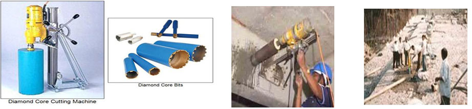
TABLE FOR CORE CUTTING TEST CERTIFICATE:
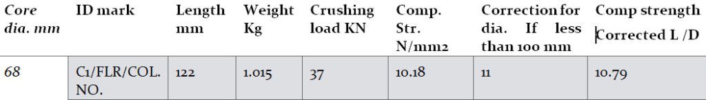
REMARKS ON CORE CUTTING TEST CERTIFICATE:
- Vide IS 456:2000 CLAUSE 17.4.3, concrete in the member represented by a core test shall be considered acceptable if the average equivalent cube strength of core is equivalent to at least 85% of the cube strength of grade of concrete specified for the corresponding age & no individual core has strength less than 75% thereof.
- Certified results refer only to the sample submitted for testing & is valid at the time of & under conditions specified herein.
Any correction makes certificate invalid
PROBE PENETRATION TEST/WINDSOR PROBE TEST OF CONCRETE- ASTM C 803
- An alloy probe having 6.3 mm dia. & 79.5 mm long is shot in concrete & exposed length after penetration is measured which relates to compressive strength of concrete as per manufacturer’s standard results
- This test has much higher energy than rebound hammer, but results are equally affected by presence of aggregates, surface undulations, crack, honeycomb & bleeding/segregation, age of concrete etc.
- This is a partially destructive test causing hole in concrete which must be filled with polymer mortar/epoxy.
LIMITATION OF PROBE PENETRATION TEST:
- Test location distance from edge of concrete member or between each test location should be @ 150 to 200 mm
- Min. depth of concrete member under test should be 3 times more than expected probe penetration depth
- Distance from reinforcement should be min. 100 mm
- This test is good for concrete grade below M40
- Brittle concrete gets fractured around probe area
- Probe cannot be kept at place, need removal & repair
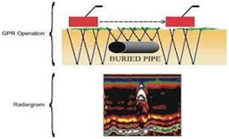
GROUND PENETRATION RADAR (GPR) TEST:
GPR COMPONENTS:
- Transmission & receiver units
- Control unit
- Display unit
- Power supplies
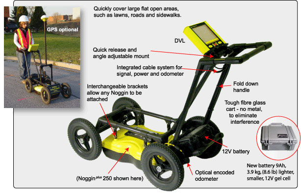
GPR APPLICATIONS & USES:
- Useful in detecting subsurface objects embedded in rock, soil, ice, fresh water, pavement & structures using electromagnetic energy using high frequency radio waves from 10 Mhz to 1 Ghz i.e. 1000 Mhz
- Also useful in detecting changes in materials properties, voids, cracks etc.
- Checks on buried pipelines, tunnels, historic objects, graves etc.
- Military use to check on unexploded ordnance or mines
HOW DEEP CAN GPR DETECT:
- Frequency Depth In Meter
- 1500 Mhz 0.5 M
- 900 Mhz 1 M
- 400 Mhz 4 M
- 270 Mhz 6M
Higher the frequency, lower the penetration but better the resolution
GPR ADVANTAGES:
- Fast & accurate
- Non destructive & saves cost of undue excavation
- Safe & easy to operate
- Digital storage of data
Long term structural health monitoring & tests on metal/wood surfaces:
For long term assessment & preventive maintenance of structures of importance where shut down & breakage/stoppage proves terribly costly
LINEAR POLARISATION/POLARISATION RESISTANCE:
- A method for corrosion monitoring generally used for marine structures reinforcement
- Polarization refer to change in open circuit potential as a result of passage of current ASTM G 15
- Small change in half cell potential of corroding bar is measured in polarization resistance test. This enables periodic enhancement in corrosion rate/speed at which bar corrodes so life can be predicted as per dia. / quantity of metal loss
- Linear relation between change in voltage & change in current per unit area of bar exist in open circuit potential
MEASUREMENT PRINCIPLE & DRAWINGS
- Polarization resistance=CHANGE IN VOLTAGE in Ohm’s/CHANGE IN VOLLAGE OF BAR SURFACE in Sq.m.
- Polarization refers to the change in the open-circuit potential as a result of the passage of current (ASTM G15)
- In the polarization resistance test, the current to cause a slight change in the value of the half- cell potential of the corroding bar is measured.
- Operating on the principle of the measurement Principle Wenner probe, the response is designed to measure the electrical resistivity of concrete or rock. A current is applied to the two outer probes, and the potential difference is measured between the two inner probes. The current is carried by ions in the pore liquid. The calculated resistivity depends on the spacing of the probes.
PRO & CONS OF POLARISATION RESISTANCE TEST:
| Advantage | Disadvantage |
| Method & equipment simple to use. | Cannot indicate the actual corrosion rate. |
| Non destructive survey on concrete members to produce potential maps. | Not applicable to epoxy coated steel bars. |
| Zones of corrosion can be identified. | Small hole to be drilled to establish contact with steel |
| Surface preparation needed. | |
| Experience operator to inter pret result. | |
| For conclusive results, there is need for other techniques like chloride content, carbonation depth etc. In conjunction. |
SIGNAL STRENGTH OF POLARISATION RESISTANCE TEST:
- Increases with increasing bar size & decreases with increasing bar cover distance
- It assumes presence of only one bar within its primary magnetic field
- As instrument is calibrated for converting signal strength to distance, even depth of cover can be indicated
Test on metal surfaces for analysis of Structural audit & NDT for modern & heritage buildings:
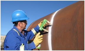
Magnetic particle induction
- Works on principle of magnet attracting metallic powder which is spread over specified area & then current is passed through test object
- Can also detect flaws in welding joints where precision is the key
- Useful in checking cracks in old / new structural steel in PEB/ Heritage structures
- Can also detect undulations/shallow subsurface discontinuity in ferromagnetic materials such as iron, nickel, cobalt & its alloys
Digital Elcometer
- Useful in checking film thickness of all types of paints like Acrylic, Alkyd, Epoxy, PU etc. on metallic surfaces
- Can check uniformity of film thickness that talks about precision in application
- Lower film thickness than specified can result into reduction in protection of surface
- Lower thickness areas can be marked for recoating by using Elcometer
- Over puddling of coating can result into delamination so such areas should be removed & coated properly
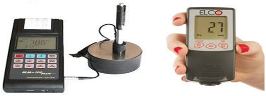
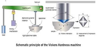
Digital metal hardness test
- Useful for ferrous & nonferrous metal surfaces to measure dry film thickness of paint/coating
- Portable hence do not require test piece to testing device unlike traditional Rockwell (HRC), Brinell (HB) or Wickers machines
Conversion from one unit to another is possible with appropriate formula
ADVANCE TESTS ON CONCRETE
ULTRASONIC PULSE ECHO FOR THIN CONCRETE SECTIONS LIKE SLAB/PAVEMENT
- Frequency used for concrete 500 Hz as max. & 20 Hz as minimum
- UPV Need access on both side of concrete member to get reliable information while Echo system is one dimensional
- Stress wave reflected from inherent defects such as crack or void is determined
- Initially developed for metals, now applicable on thin walls/slabs
- Low frequencies are used in case of concrete
- IMPACT ECHO method ASTM C1383 is also used
IMPACT ECHO METHOD
- This can indicate anomalies in plain/RCC/PT concrete 5/Masonry with indicative locations & extent of flaws like cracks, delamination, voids, honeycombing, debonding etc.
- Useful in slabs, pavement, walls, deck, roads & layered plates like asphalt with concrete overlay, hollow pipes, tanks, grouted tendon ducts etc.
- Can measure concrete thickness with accuracy up to 3%
COMPARISON OF IMPACT ECHO TO UPV
- Impact echo does not have need of heavy transmitter & receiver
- However, impact echo does not have directionality like UPV as IE energy propagates in all directions so reflections are received from all directions. Exact location finding is thus difficult
Spectral analysis of surface waves & seismic reflections(SASW) FOR ROADS
- Developed between 1960 & 1970, then research was dormant till 1980 which was again taken up at University of Texas Austin
- Method is used to determine stiffness profile of soil, asphalt or concrete pavements besides concrete str. Members & also for checking changes in elastic properties of concrete during curing, detection of voids & internal damages
PRINCIPLES OF SASW
- An impact is used to generate R wave/ surface wave & 2 receivers are used to monitor its motion; Signals are processed & calculated as per mfrs. Scheme are used to ascertain stiffness of layer under testing
- Like Impact echo, R waves also contain range of components of diff frequencies/ wavelengths
SASW ADVANTAGE over other similar methods
| Method | Advantage |
| Ultrasonic through directs transmission (pulse velocity) UPV | Portable equipments is available relatively carry to time |
| Ultrasonic echo | Access to only one face is needed to provide information on depth of defects. |
| Impact echo | Access to only one face is needed, equipment is commercially available. Capable of locating a variety of defects. Does not requires coupling materials |
| Spectral analysis of surface waves | Capable of determining the elastic properties of layered systems, such is pavement micro layered good & poor-quality concrete |
LIMITATIONS
| Method | Limitation |
| Ultrasonic through directs transmission (pulse velocity) UPV | Require access to sides of members, does not provide information on depth of defects. |
| Ultrasonic echo/pile integrity test | Applicable is limited members thickness not commercially available, experience operator is required. |
| Impact echo | Experience operator is required: current instrumentation limited to testing members less than 2m thick. |
| Spectral analysis of surface waves. | Experience operator is required: involves complex signal processing. |
PILE INTEGRITY/ ULTRASONIC ECHO TEST
- Impact is made on the pile/ raft foundation top to generate stress waves which travel through height of str. Member & return to transducer/ accelerometer coupled on head of foundation under testing where time taken is measured
- Time of impact generation & vertical movement of pile/raft concrete due to impact are recorded by digital data acquisition devices like oscilloscopes periodically.
- Results will tell story of discontinuity/integrity of foundation
Structural health monitoring
For long term assessment & preventive maintenance of structures of importance where shut down & breakage/stoppage proves terribly costly
LINEAR POLARISATION/ POLARISATION RESISTANCE
- A method for corrosion monitoring generally used for marine structures reinforcement
- Polarisation refer to change in open circuit potential as a result of passage of current ASTM G 15
- Small change in half cell potential of corroding bar is measured in polarisation resistance test. This enables periodic enhancement in corrosion rate/speed at which bar corrodes so life can be predicted as per dia. / quantity of metal loss
- Linear relation between change in voltage & change in current per unit area of bar exist in open circuit potential
MEASUREMENT PRINCIPLE & DRAWINGS
Polarisation resistance=CHANGE IN VOLTAGE in Ohm’s/CHANGE IN VOLLAGE OF BAR SURFACE in Sq.m.
LINEAR POLARIZATION OR POLARIZATION RESISTANCE
- Polarization refers to the change in the open-circuit potential as a result of the passage of current (ASTM G15)
- In the polarization resistance test, the current to cause a small change in the value of the half- cell potential of the corroding bar is measured.
- Operating on the principle of the measurement Principle Wenner probe, the response is designed to measure the electrical resistivity of concrete or rock. A current is applied to the two outer probes, and the potential difference is measured between the two inner probes. The current is carried by ions in the pore liquid. The calculated resistivity depends on the spacing of the probes.
POLARIZATION RESISTANCE
- Enables the measurement of the instantaneous corrosion rate.
- Quantities the amount of metal per unit of area being corroded in a particular instant.
- For a slight change in the open circuit potential, a linear relationship exists between the change in voltage F, and the change in current per unit area of but surface i.
- Polarization resistance R = F / i
- Units are (ohms* area)
Relation between corrosion rate & damage severity
| Corrosion rate (MA/M2) | Severity of damage |
| <2 | No corrosion damaged expected |
| 2-10 | Corrosion damage possible in 10-15 years |
| 10-100 | Corrosion damage possible in 2-10 years |
| <100 | Corrosion damage possible in less than 2 years |
| Assumes corrosion rate is constant with time. | In practice, not necessary so |
PRO & CONS OF POLARISATION RESISTANCE TEST
| Advantage | Disadvantage |
| Method & equipment sample to use. | Cannot indicate the actual corrosion rate. |
| Non-destructive survey on concrete members to produce potential maps. | Not applicable to epoxy coated steel bars. |
| Zones of corrosion can be identified. | Small hole to be drilled to establish contact with steel |
| Surface preparation needed. | |
| Experience operator to interpret results. | |
| For conclusive results, needs other techniques like chloride content, carbonation depth etc. In conjunction. |
SIGNAL STRENGTH
- Increases with increasing bar size & decreases with increasing bar cover distance
- It assumes presence of only one bar within its primary magnetic field
- As instrument is calibrated for converting signal strength to distance, even depth of cover can be indicated
Ground penetration radar test
GPR Applications & uses
- Useful in detecting sub surface objects embedded in rock, soil, ice, fresh water, pavement & structures using electromagnetic energy using high frequency radio waves from 10 Mhz to 1 Ghz i.e. 1000 Mhz
- Also useful in detecting changes in materials properties, voids, cracks etc.
- Checks on buried pipelines, tunnels, historic objects, graves etc.
- Military use to check on unexploded ordnance or mine
How deep can GPR Detect
Frequency Depth in Meter
- 1500 Mhz 0.5 M
- 900 Mhz 1 M
- 400 Mhz 4 M
- 270 Mhz 6M
Higher the frequency, lower the penetration but better the resolution
GPR Advantages
- Fast & accurate
- Nondestructive & saves cost of undue excavation
- Safe & easy to operate
- Digital storage of data
GPR Components
- Transmission & receiver units
- Control unit
- Display unit
- Power supplies
DRAWINGS & DOCUMENTS REQUIRED FOR STRUCTURAL AUDIT REPORT:
- Building layout plan
- Column location plan
- Floor wise section plan showing all rooms for distress mapping
- Photographic representation of various building components
- Society/Building registration certificate
INCLUSIONS IN STRUCTURAL AUDIT REPORT:
- Stilt/ ground floor columns & all accessible str. Members
- Building external & internal walls & its plaster, Overhead & underground water tanks, Lift shaft & LMR, Staircase & Head room, Parapet walls & coping, Pump room, compound wall, compound paving, common area plumbing & drainage, compound drainage, stair steps etc.
- Roof, purlins, doors, windows, ducts, shafts, grills
- Allied works like lobby decoration, common area electrification etc. Foundations, cooling towers, silos etc. in industrial structures
- Load testing, soil testing, corrosion monitoring devices installation for bridges/marine structures
- Thermal Infra-red imaging of buildings
- Industry specific testing
CHALLENGES DURING STRUCTURAL AUDIT:
- MCGM guidelines are not clear so not all necessary tests are conducted on structures unless specified. Neither client nor an architect is aware of test requirements & testing agency is seldom consulted before calling for quotes for testing. Many times, scope of testing agencies or number of tests required are vague hence scrupulous agencies take advantage & serve half baked information to clients which makes decision making difficult/blur.
- Separate registrations at BMC, NMMC, TMC, MBMC & KDMC are required so many of the times, competent agencies are unable to participate in bidding on site for their technical & commercial capabilities. Few departments make tender conditions suiting only chosen few agencies to avoid genuine competition.
- Trained workforce not available i.e. N.D.T. is not part of training at Bldg. maintenance courses, Civil Engg. Or architecture
- Charges vary highly variable as there is no standardization of equipment specifications & workforce experience, number of tests & so on.
- Report format not standardized so detailing is seldom attended to. Reports for the same structure vary from 2 pages to 70 pages. Conclusions given are ambiguous which leads to wrong decisions / priorities.
- Expectation levels vary by every client so repair/restoration v/s redevelopment decisions are taken irrespective of outcome of report since comparison & budget evaluations are left to individual imaginations. Clients are from non-technical background hence Repair/ redevelopment options are left to people where decisions are taken based on groups, prides & prejudices, financial availability (actual or perceived)
- Options v/s Durability/ life expectancy of structure are not compared properly hence budget comparison takes driving seat during meetings. Many times, Partial works carried our despite recommendations by consultant
- Executing agencies / contractors sometimes are non-technical. This seriously affects quality of work & industry becomes victim & gets a bad name.
- Unorganized industry with no council / guiding /controlling agency unlike Doctors, architects & chartered accountants where professional bodies control practicing. This results in many unqualified agencies getting into practice & spoiling the name of the profession.
RAY OF HOPE & OPPORTUNITIES:
- There is Better acceptability of Str. Audits due to notices from municipal corporations & Report submission requirement prior to repairs/ redevelopment & factories act prerequisite before sanctions of new construction/ expansions
- Collapses/accidents of buildings have induced fear & awareness amongst stakeholders to get a health assessment of structures done & to act upon recommendations of structural audit reports therein.
- Awareness by seminars/presentations/federations of housing societies added fuel to willingness & curiosity of getting structural audit done
FINAL WORD:
- Structural audits are here to stay & grow
- Architects & civil Engineers can work in conjunction with structural engineers to make it work benefitting all concerned
- Such pathological confirmatory reports can give practicing architects insight while renovating / reconstructing/adding/altering buildings in question
- Heritage restoration is separate fraternity & can be discussed in length while meeting again
- Structural analysis is next step to follow to check adequacy of design at current status & to design extension/change of user/decision on repairs/redevelopment
Article contributed by – Jatin Ambani ADVICE CONSULTANTS, MUMBAI, INDIA.
CONSULTING CIVIL/STRUCTURAL ENGINEERS & ARCHITECTS-STRUCTURAL AUDIT, BUILDING RESTORATION , NONDESTRUCTIVE TESTING & HERITAGE CONSERVATION