Concrete has very good compressive strength and almost negligible tensile strength. Hence, steel reinforcement is used on the tensile side of concrete. Thus, singly reinforced beams reinforced on the tensile face are good both in compression and tension. However, these beams have their respective limiting moments of resistance with specified width, depth and grades of concrete and steel. The amount of steel reinforcement needed is known as Ast,lim. Problem will arise, therefore, if such a section is subjected to a bending moment greater than its limiting moment of resistance as a singly reinforced section.
There are two ways to solve the problem. First, we may increase the depth of the beam, which may not be feasible in many situations. In those cases, it is possible to increase both the compressive and tensile forces of the beam by providing steel reinforcement in the compression face and additional reinforcement in the tension face of the beam without increasing the depth. The total compressive force of such beams comprises
- force due to concrete in compression and
- (force due to steel in compression.
The tensile force also has two components:
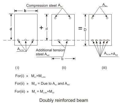
(i) the first provided which is equal to the compressive force of concrete in compression. The second part is due to the additional steel in tension – its force will be equal to the compressive force of steel in compression. Such reinforced concrete beams having steel reinforcement both on tensile and compressive faces are known as doubly reinforced beams.
Doubly reinforced beams, therefore, have more resistance than the singly reinforced beams of the same depth for particular grades of steel and concrete. In many practical situations, architectural or functional requirements may restrict the overall depth of the beams. However, other than in doubly reinforced beams compression steel reinforcement is provided when:
(i) Some sections of a continuous beam with moving loads undergo change of sign of the bending moment which makes the compression zone as tension zone or vice versa.
(ii) The ductility requirement has to be followed.
(iii) The reduction of long term deflection is needed.
It may be noted that even in so called singly reinforced beams there would be longitudinal hanger bars in the compression zone for locating and fixing stirrups.
Assumptions;
(i) The assumptions of sec. 3.4.2 of Lesson 4 are also applicable here.
(ii) Provision of compression steel ensures ductile failure and hence, the limitations of x/d ratios need not be strictly followed here.
(iii) The stress-strain relationship of steel in compression is the same as that in tension. So, the yield stress of steel in compression is 0.87 fy.
Basic Principle
The moment of resistance Mu of the doubly reinforced beam consists of
(i) Mu,lim of singly reinforced beam and
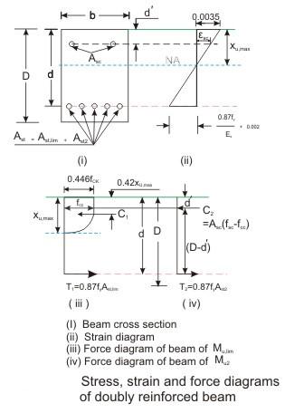
(ii) Mu2 because of equal and opposite compression and tension forces (C2 and T2) due to additional steel reinforcement on compression and tension faces of the beam. Thus, the moment of resistance Mu of a doubly reinforced beam is
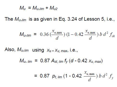
The additional moment Mu2 can be expressed in two ways: considering
(i) the compressive force C2 due to compression steel and
(ii) the tensile force T2 due to additional steel on tension face. In both the equations, the lever arm is (d – d’). Thus, we have
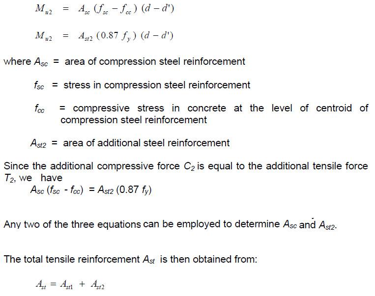
Determination of fsc and fcc
It is seen that the values of fsc and fcc should be known before calculating Asc. The following procedure may be followed to determine the value of fsc and fcc for the design type of problems (and not for analysing a given section). For the design problem the depth of the neutral axis may be taken as xu,max as shown in Fig. 4.8.2. From Fig. 4.8.2, the strain at the level of compression steel reinforcement εsc may be written as

The stress in compression steel fsc is corresponding to the strain εsc of Eq. and is determined for
(a) mild steel and
(b) cold worked bars Fe 415 and 500 as given below:
(a) Mild steel Fe 250
The strain at the design yield stress of 217.39 N/mm2 (fd = 0.87 fy ) is 0.0010869 (= 217.39/Es). The fsc is determined from the idealised stress-strain diagram of mild steel after computing the value of εsc from Eq. as follows:
(i) If the computed value of εsc ≤ 0.0010869, fsc = εsc Es = 2 (105) εsc
(ii) If the computed value of εsc > 0.0010869, fsc = 217.39 N/mm2.
(b) Cold worked bars Fe 415 and Fe 500
It shows that stress is proportional to strain up to a stress of 0.8 fy. The stress-strain curve for the design purpose is obtained by substituting fyd for fy in the figure up to 0.8 fyd. Thereafter, from 0.8 fyd to fyd, Table A of SP-16 gives the values of total strains and design stresses for Fe 415 and Fe 500. Table presents these values as a ready reference here.
Table Values of fsc and εsc
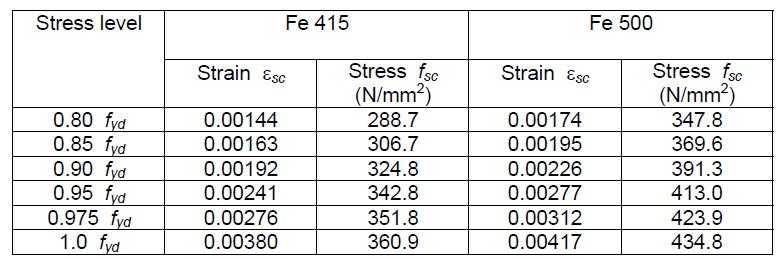
Linear interpolation may be done for intermediate values.
The above procedure has been much simplified for the cold worked bars by presenting the values of fsc of compression steel in doubly reinforced beams for different values of d’/d only taking the practical aspects into consideration. In most of the doubly reinforced beams, d’/d has been found to be between 0.05 and 0.2. Accordingly, values of fsc can be computed from Table after determining the value of εsc from Eq. for known values of d’/d as 0.05, 0.10, 0.15 and 0.2. Table F of SP-16 presents these values of fsc for four values of d’/d (0.05, 0.10, 0.15 and 0.2) of Fe 415 and Fe 500. Table below, however, includes Fe 250 also whose fsc values are computed along with those of Fe 415 and Fe 500. This table is very useful and easy to determine the fsc from the given value of d’/d. The table also includes strain values at yield which are explained below:
(i) The strain at yield of Fe 250 =


Table Values of fsc for different values of d’/d

Minimum and maximum steel
In compression
There is no stipulation in IS 456 regarding the minimum compression steel in doubly reinforced beams. However, hangers and other bars provided up to 0.2% of the whole area of cross section may be necessary for creep and shrinkage of concrete. Accordingly, these bars are not considered as compression reinforcement. From the practical aspects of consideration, therefore, the minimum steel as compression reinforcement should be at least 0.4% of the area of concrete in compression or 0.2% of the whole cross-sectional area of the beam so that the doubly reinforced beam can take care of the extra loads in addition to resisting the effects of creep and shrinkage of concrete.
The maximum compression steel shall not exceed 4 percent of the whole area of cross-section of the beam as given in cl. 26.5.1.2 of IS 456.
In tension
As stipulated in cl. 26.5.1.1(a) and (b) of IS 456, the minimum amount of tensile reinforcement shall be at least (0.85 bd/fy) and the maximum area of tension reinforcement shall not exceed (0.04 bD).
The singly reinforced beams shall have Ast normally not exceeding 75 to 80% of Ast,lim so that xu remains less than xu,max with a view to ensuring ductile failure. However, in the case of doubly reinforced beams, the ductile failure is ensured with the presence of compression steel. Thus, the depth of the neutral axis may be taken as xu, max if the beam is over-reinforced. Accordingly, the Ast1 part of tension steel can go up to Ast, lim and the additional tension steel Ast2 is provided for the additional moment Mu – Mu, lim. The quantities of Ast1 and Ast2 together form the total Ast, which shall not exceed 0.04 bD.
Types of problems and steps of solution
Similar to the singly reinforced beams, the doubly reinforced beams have two types of problems:
(i) design type and
(ii) analysis type.
The different steps of solutions of these problems are taken up separately.
Design type of problems
In the design type of problems, the given data are b, d, D, grades of concrete and steel. The designer has to determine Asc and Ast of the beam from the given factored moment. These problems can be solved by two ways: (i) use of the equations developed for the doubly reinforced beams, named here as direct computation method, (ii) use of charts and tables of SP-16.
(a) Direct computation method
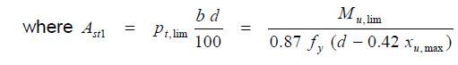
Step 1: To determine Mu, lim and Ast, lim from Eqs. respectively.
Step 2: To determine Mu2, Asc, Ast2 and Ast from Eqs. respectively.
Step 3: To check for minimum and maximum reinforcement in compression and tension
Step 4: To select the number and diameter of bars from known values of Asc and Ast.
(b) Use of SP table
Tables present the pt and pc of doubly reinforced sections for d’/d = 0.05, 0.10, 0.15 and 0.2 for different fck and fy values against Mu /bd2. The values of pt and pc are obtained directly by selecting the proper table with known values of Mu/bd2 and d’/d.
Analysis type of problems
In the analysis type of problems, the data given are b, d, d’, D, fck, fy, Asc and Ast . It is required to determine the moment of resistance Mu of such beams. These problems can be solved:
(i) by direct computation method and
(ii) by using tables of SP-16.
(a) Direct computation method
Step 1: To check if the beam is under-reinforced or over-reinforced.

(b) Use of tables of SP-16
As mentioned earlier Tables are needed for the doubly reinforced beams. First, the needed parameters d’/d, pt and pc are calculated. Thereafter, Mu/bd2 is computed in two stages: first, using d’/d and pt and then using d’/d and pc . The lower value of Mu is the moment of resistance of the beam.
Conclusion
The article thoroughly explores the principles, assumptions, and the determination of key steel parameters such as fsc and fcc, crucial for designing doubly reinforced beams. It also discusses minimum and maximum steel requirements, distinguishes between under-reinforced and over-reinforced beams, and provides practical solutions for engineers and designers.
About the author;
The author has more than three decades of experience in multi-disciplinary transactions ranging from industrial projects to real estate development projects. He has expertise in planning, undertaking demand assessment studies, transaction services, project execution, business development, etc.