
Statically indeterminate structures made of reinforced concrete like fixed ended one span beams, continuous beams and frames are designed considering internal forces like bending moment, shear force and axial thrust obtained from structural analysis. Either one or several sections of these structures may have peak values of the internal forces, which are designated as critical sections. These sections are dimensioned and reinforced accordingly. Flexural members, however, do not collapse immediately as soon as the loads at a particular section cause bending moment exceeding the maximum resisting moment capacity of that section. Instead, that section starts rotating at an almost constant moment. This is known as formation of plastic hinges at that section reaching its maximum resisting moment capacity. The section then transfers loads to other sections if the applied loads are further increased. This process continues till the structures have plastic binges at sufficient sections to form a failure mechanism when it actually collapses. However, significant transfer of loads has occurred before the collapse of the structure. This transfer of loads after the formation of the first plastic hinge at the section having the highest bending moment till the collapse of the structure is known as redistribution of moments. By this process, therefore, the structure continues to accommodate higher loads before it collapses.
The elastic bending moment diagram prior to the formation of the first plastic hinge and the final bending moment diagram just before the collapse are far different. The ratio of the negative to positive elastic bending moments is no longer valid. The development of plastic hinges depends on the available plastic moment capacity at critical sections. It is worth mentioning that the redistribution of moment is possible if the section forming the plastic hinge has the ability to rotate at constant moment, which depends on the amount of reinforcement actually provided at that section. The section must be under-reinforced and should have sufficient ductility.
This phenomenon is well known in steel structures. However, the redistribution of momentum has also been confirmed in reinforced concrete structure by experimental investigations. It is also a fact that reinforced concrete structures have comparatively lower capacity to rotate than steel structures. Yet, this phenomenon is drawing the attention of the designers. Presently, design codes of most of the countries allow the redistribution up to a maximum limit because of the following advantages:
1) It gives a more realistic picture of the actual load carrying capacity of the indeterminate structure.
2) Structures designed considering the redistribution of moment (though limited) would result in economy as the actual load capacity is higher than that we determine from any elastic analysis.
3) The designer enjoys the freedom of modifying the design bending moments within limits. These adjustments are sometimes helpful in reducing the reinforcing bars, which are crowded, especially at locations of high bending moment.
Two Span Beam
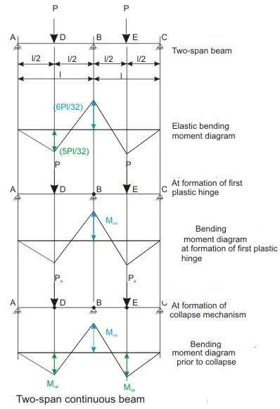
Let us take up a two-span beam of uniform cross-section, as shown in Fig. with the following assumptions:
a) The ultimate moments of resistance of sections at B and D are –Mun and +Mup, respectively.
b) There will not be any premature shear failure so that the sections can attain the respective ultimate moment capacity.
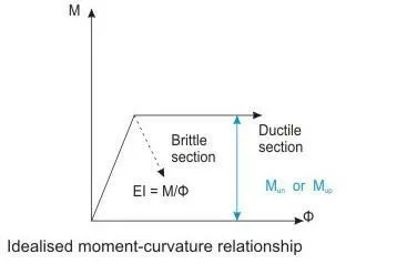
c) The moment-curvature relationship for the ductile sections is the idealised bilinear as shown in Fig. It may be noted that for all practical purposes only a limited rotation will take place.
d) All sections of the beam have the same constant flexural rigidity up to the ultimate moment and moment remains constant at the ultimate moment with increasing curvature.
e) The self-weight of the beam is neglected.
The beam is subjected to two point loads of magnitude P each and acting at distances of l/2 from the two supports A and C, as shown. The elastic bending moment diagram is shown in Fig.. On increasing the loads P, the ultimate moment of resistance Mun of cross-section at B will be reached at the support first before reaching at other sections, which is shown in Fig.. The plastic hinge will be formed at the cross-section B. The two point loads P can still be increased as long as the plastic hinge at B will rotate sufficiently. If the cross-section at B is brittle, the load will decrease fast and the beam will fail suddenly. Hence, the beam will not carry any additional load. The cross-section at B has to be ductile so that it undergoes rotation at the constant moment of resistance, which will enable the beam to carry additional loads. This increase of load will continue until the maximum positive moments in the span (at D and E) reach Mup, as shown in Fig. when plastic hinges will form at D and E also. The three plastic hinges at B, D and E will form the collapse mechanism. The structure will fail at this stage carrying much higher loads. It is important to note that the requirement of equilibrium will be satisfied at all stages, i.e., Mp and Mn , during the elastic phase, will follow the equation:
Mp + 0.5 Mn = Pl/4
From the structural analysis of the beam of Fig., we know that:
Mn = 6 Pl / 32 and Mp = 5 Pl / 32.
Substituting these values in Eq. We find that the equation is satisfied where Pl/4 is the maximum positive moment of a simply supported beam having a load P at the centre of the beam. From the above values of Mn and Mp (= 6 Pl/32 and 5 Pl/32, respectively), we also note that:
Mn / Mp = 1.2
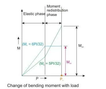
As the loads are increased till the formation of the first plastic hinge at B, this ratio of Mn /Mp as 1.2 will be maintained, as shown in Fig.. This phase is known as the elastic phase when the bending moment increases with increasing loads maintaining the ratio of Mn / Mp as 1.2.
With further increase of the loads, the plastic hinge at B will rotate at the constant moment Mun and positive moments at D and E will increase as shown in Fig. This phase is known as the moment redistribution phase as the loads are now transferred to sections, which have less moment. However, the cross-section at B must have the ability to sustain the required plastic rotation at this stage with increasing loads. As the value of Mp is now increasing when Mn is remaining constant, the ratio of Mn / Mp will not be 1.2 any more. Thus, in the redistribution phase, the additional moments at higher loads are to be redistributed to the support and mid-span in such a manner that we get a similar equation like Eq. i.e.
Mup + 0.5 Mun =Pl/4 (15.3)
which means that, after the redistribution
Mun = Mn –M
where M is some amount of moment by which negative moment at the support is reduced. From Eqs. 15.3 and 15.4, we have: Mup = Pl/4 – 0.5 Mun = Pl/4 – 0.5 (Mn-M) = (Pl/4 – 0.5 Mn) + 0.5 M = Mp + 0.5 M, which we get by substituting Mp = Pl/4 – 0.5 Mn from Eq. 15.1. Therefore, we have:
Mup = Mp + 0.5 M
Thus, in the moment redistribution, if we reduce some amount M from the negative moment Mun at support as in Eq. we have to add 0.5 M to the span moment Mp to get the Mup as in Eq. The redistributed moments Mun and Mup satisfy the equilibrium condition of Eq. Similar equilibrium condition is also satisfied at the elastic stage by the Mn and Mp as in Eq. .
The amount of moment M which will be reduced from the negative support moment depends on the rotational capacity as per the actual reinforcement provided in the cross-section. Furthermore, the deformation of the support should be within acceptable limits under service loads.
In the extreme case, if the negative moment at the support Mun is reduced to zero, i.e., M = Mn , we have from Eq.:
Mup = Mp + 0.5 Mn = Pl/4
That is, the unreinforced central support will crack and the continuous beam will behave as two simply supported beams.
Thus, the choice of the bending moment diagram after the redistribution should satisfy the equilibrium of internal forces and external loads. Moreover, it must ensure the following:
1. The plastic rotations required at the critical sections should not exceed the amount the sections can sustain.
2. The extent of cracking or the amount of deformation should not make the performance unsatisfactory under service loads.
The redistribution of moments is permitted if the analysis of forces and moments is done following linear elastic behaviour. Analysis by linear elastic behaviour is a logical procedure in the working stress method of design where the design concept is based on the assumptions of linear elastic behaviour of materials up to the level of recommended safe stresses. However, analysis by linear elastic theory and design by the limit state of collapse appear to be somewhat contradictory. At the stress levels of 0.87 fy for steel and 0.67 fck for concrete, the strains are not linearly related. Unfortunately, till now there is no such analysis, which takes into account the complex behaviour of reinforced concrete just before the collapse. Accordingly, the elastic theory of analysis of forces and moments cannot be avoided at present except for the slabs.
Moreover, unlike steel structures, the cross-section forming the first plastic hinge in reinforced concrete members undergoes limited rotations, which is insufficient for other sections to attain the desired Mup. Therefore, full redistribution has been restricted in the design of reinforced concrete members. These restrictions and stipulations of IS Codes are taken up in the next section.
Recommendations of IS 456
IS 456 recommends the redistribution of moments during the analysis provided the analysis is done by linear elastic theory. Such redistribution of moments is not permitted when either simplified analysis is done or coefficients of cl.22.5 of IS 456 are used to determine the moments.
In the working stress method, cl. B-1.2 of IS 456 stipulates that the moments over the supports for any assumed arrangement of loading, including the dead load moments may each be increased or decreased by not more than 15 per cent, provided that these modified moments over the supports are used for the calculation of the corresponding moments in the spans.
In the limit state of collapse method, cl.37.1 of IS 456 recommends the redistribution of the calculated moment in continuous beams and frames satisfying the following conditions:
1. Equilibrium between the internal forces and the external loads should be maintained.
2. The ultimate moment of resistance provided at any cross-section of a member after the redistribution should not be less than 70 per cent of the moment at that cross-section obtained from an elastic maximum moment diagram covering all appropriate combinations of loads.
3. The elastic moment at any cross-section in a member due to a particular combination of loads shall not be reduced by more than 30 percent of the numerically largest moment given anywhere by the elastic maximum moment diagram for the particular member, covering all appropriate combinations of loads.
4. Cross-sections having moment capacity after redistribution less than that of the elastic maximum moment shall satisfy the relationship:
(xu / d) + (δM / 100) ≤ 0.6
where
xu = depth of the neutral axis,
d = effective depth, and
δM = percentage reduction in moment.
5. Thirty per cent reduction in moment permitted in 3 above shall be restricted to ten per cent for structures in which the structural frames provide lateral stability.
Explanations of the Conditions Stipulated in IS Code
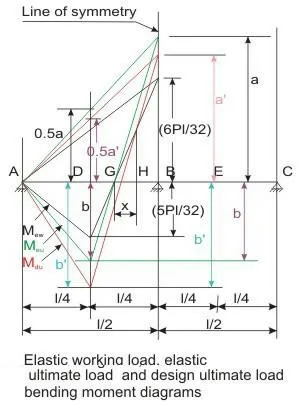
The first condition of maintaining the equilibrium between internal forces and external loads is explained in sec.15.38.2 taking up a two-span continuous beam. For the other conditions, let us use the following notations for the sake of brevity:
Mew = elastic bending moment under working loads,
Meu = elastic bending moment under design loads i.e., the factored loads considering partial safety factor of loads γf,
Mdu = design factored moment after redistribution, and
δM = percentage reduction in Meu.
Since γf = 1.5, we can write
Meu = 1.5 Mew
The second condition of cl.37.1 of IS 456, as given in sec., is expressed as
Mdu ≥ 0.7 Meu
Beeby has reported that the redistribution as given in Eq. is possible before the lower bound rotation capacity is reached Thus, Eq. ensures the first criterion of the redistribution of moments in reinforced concrete structures as given in sec. Equation also satisfies other requirements as explained below.
Using the value of Meu from Eq. into Eq. we have
Mdu ≥ 0.7 (1.5 Mew) ≥ 1.05 Mew (15.10)
This ensures that the design factored moments are greater than the elastic moments everywhere in the structures. Figure above presents three bending moment diagrams: (i) elastic moment under working loads (Mew), (ii) elastic moment under ultimate loads (Meu) and (iii) design moment under ultimate loads (Mdu) of the two-span beam of Fig.. The moment diagram after the redistribution (Mdu) satisfies the condition of Eq. 15.1 such that
b + 0.5 a = b′ + 0.5 a′ (15.11)
However, Mdu diagram is not satisfying the requirement of Eq. as in the zone GH of length x, the negative moment after redistribution is less than the negative moment under working loads. To satisfy Eq. the bending moment in the zone should be as per Mew.
We now take up the fourth condition of cl.37.1 of IS 456 and given in sec. which is expressed in Eq. as
(xu/d) + (δM / 100) ≤ 0.6 (15.7)
This equation ensures that the cross-section of the member is under-reinforced, as explained below.
Allowing the maximum redistribution of thirty per cent as per the third condition of sec., we have δM/100 = 0.3. Substituting this in Eq., we get xu/d ≤0.3. For (δM/100) less than thirty per cent, the corresponding xu/d can be determined from Eq. The values of xu,max/d for the three grades of steel are given in Table. It is easy to verify that permitting the redistribution of thirty per cent, the cross-sections remain under-reinforced. This ensures a low amount of steel reinforcement to have a smaller value of xu which will give higher value of the rotation φ as the rotation φ = 0.0035/xu.
About the author;
The author has more than three decades of experience in multi-disciplinary transactions ranging from industrial projects to real estate development projects. Expertise in planning, undertaking demand assessment studies, transaction services, project execution, business development, etc. including marketing strategies based on technical market analysis, feasibility studies, program requirement derivation and fund and investor sourcing.
Almost 7 years experienced senior professional with project & construction management expertise in large projects for IT, Commercial, Industrial, residential sectors, etc. and more than 18 years of heavy engineering industrial projects like Fertilizers, Oil & Gas, Petrochemicals, etc.