


Trenchless technology is the science of installing, repairing and renewing underground pipes, ducts and cables using techniques which minimize or eliminate the need for excavation. It can reduce environmental damage, Social costs and produce in alternative to the open trench method of installation, renewal and repair it includes in, development of all kinds of underground napping techniques, tunnelling devices and specialist materials and equipment.
Introduction
Trenchless technology consists of the methods, materials, and equipment used for replacing, rehabilitating, or installing pipes with little or no excavation of the ground above. It also makes it possible to install the utilities under rivers, highways, canals and other obstacles with no disruption of flow and with minimum or no damage to the environment.
CRITICAL REVIEW
TYPES OF TRENCHLESS TECHNOLOGY METHODS
Trenchless technology methods systems have been categorized into two groups:
- New installation
- Rehabilitation and Renovation
NEW INSTALLATION
Methods for installation of a new pipeline or duct, including dealing with service connection are:
- Micro tunnelling
- Horizontal directional drilling
- Short drive system
- Guided drilling
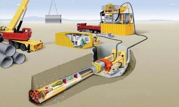
MICRO TUNNELING
Controlled excavation – steerable – Less than 1000mm diameter – Medium length
Micro tunnelling is a term which is used to describe remotely controlled mechanical tunnelling systems where the spoil is removed from the cutting head within the new pipeline which is advanced by pipe jacking.
Micro tunnelling machines have now been developed to work from drive shafts in almost all types of ground conditions. The cutting head has to be carefully selected to deal with the expected ground conditions, with the appropriate cutting tools and crushing devices for the range of gravels, sands, slits, and clays.
The only excavating required from the service is to drive and receptions shafts. Spoil may be removed from the face by an auger running through the newly installed pipeline to a skip in the base of the drive shaft.
Alternatively, water or bentonite may be used to convert the soil into slurry at the cutting face. The slurry is less then pumped to the surface where the solids are separated before disposal.
Micro tunnelling is used extensively in sewerage work where surface disruption has to be minimized. Machines are now available to drive 100mm or more in soft ground for sizes 100mm diameter upwards. From drive shafts of less than 3mm diameter.
Micro tunnelling system has been developed in which temporary steel tubes are jacked in and removed at the next manhole position, the new pipeline following in the established bore. In micro tunnelling, the only indication on the surface is the presence of a control container with a hoist for lowering pipes into the drive shafts. Noise levels and traffic disruption are minimized.
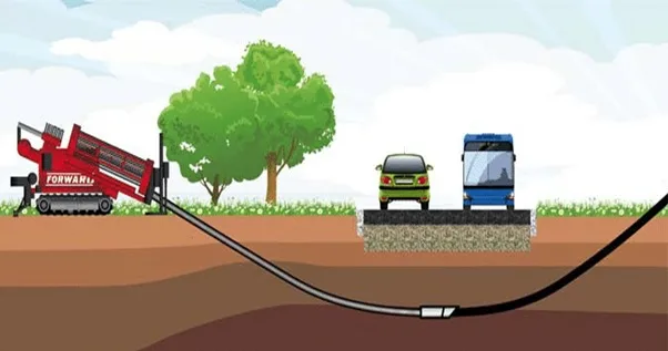
- HORIZONTAL DIRECTIONAL DRILLING
Steerable heavy, powerful rig-Large size range –Long distances
Horizontal drilling systems are nowadays widely used for installing pressure pipes under major obstacles such a motorway intersection, large rivers and airport runways.
A small rotating and steerable drill bit is launched from the surface at an angle 10-15 and is used to drill 90mm mud filled diameter hole. During the drilling operation a 125mm diameter wash over pipe is drilled over the pilot string and following some 100mm behind the head. Alternate drilling then continues on the pilot string is removed and the bore is enlarged by a rotating barrel reamer attached to and pulled back by the wash over pipe, drilling mud being used to lusted away the cuttings and to support the reamed hole. Subsequent caming continues until the required diameter is achieved. The product pipe is less than attached to the reaming head and pulled through the bore drives of more than 1.5km and of up to 1200mm diameter have been carried out.
- SHORT DRIVE SYSTEMS
Auger Boring utilizes a rotating head to excavate the soil, which is transported by auger flights operating in a casing to the drive pit. The head is recovered at an exit pit or in the trench cut for the adjacent length of pipeline. Auger boring is used in the range of 100- 1000mm diameter.
Impact Moling in which a percussive mole is launched from a drive pit to displace the soil and from a bore is widely used. The new conduct is normally drawn in behind the mole. They are used to install services for all utilities.
Rod Pushing is a technique in which a bore of about 50mm diameter is formed by displacement. A rod is advanced by a straight hydraulic push and the pilot hole may be back reamed to the required size. The technique is used for the installation of pipes and conduits up to 15mm diameter over lengths of 30-40mm.
Pipe ramming and Thrust boring are similar processes where a casting, usually steel, is driven through the ground from the drive pit to the exit pit. Accumulating spoil is removed by compressed air and water after completing the bore. Pipe ramming is suitable for most types of soil but not suitable where there are solid rock formations. It is said to be a cost saving alternative to open trenching, angering or pipe jacking methods. Usually pipes up to 2000mm diameter can be laid using this technique depending upon the equipment uses.
- GUIDED DRILLING
Steerable small rig-Sallow drilling-Medium length
Guide drilling employs an excavation or soil displacement with compact lightweight rig for rapid mobilization. Small diameter jets mechanized cutting tools or displacement heads attached to a flexible drill string are positioned to form a bore as the head is thrust forward. The drilling head is launched from the surface at an inclined angle. Controlling the orientation of a slant face at the head affects steering in both vertical and horizontal planes. Monitoring of the alignment takes place using a transmitter in the head and a locating device at ground level. I having established the pilot bore; back reaming equipment is drawn through the hole to enable it to accept the product pipe, duct, or cable using an impact mole.
2. RENOVATION AND REHABILITATION
Methods including are:
- Pipe bursting
- Pipe eating
- Retaining the existing pipe
- Localized repair
1.PIPE BURSTING
New for old without trenching – Size for size and upsize capability
In this method an existing pipeline can be replaced with a pipeline of the same or larger dimension without opening up the ground. It is especially useful in areas where the load on the system is more than the existing pipe can handle and replacement is required. The method uses a mole as a bursting head that is drawn through the existing pipe crushing it as it moves forward and replacing it with a new PE (polyethylene) pipe. The main advantage of this system is that a small power source can be used to drive the mole with minimum time. Upsizing from 100mm diameter to 225mm diameter is now well established, and pipes of up to 600mm diameter have been replaced.
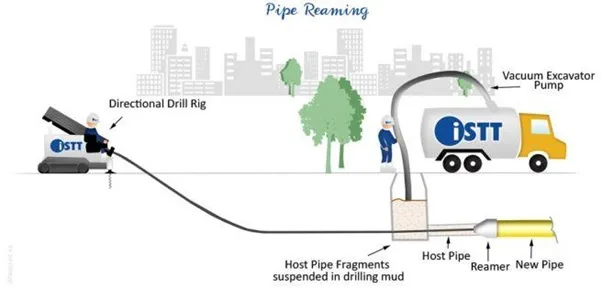
2.PIPE EATING
New for old without trenching – Enlargement – Steerable
Pipe eating is an online micro tunnelled replacement technique. The existing defective pipeline is crushed and removed through the new pipeline. Lateral connections must be disconnected in advance and may be replaced by rider sewers or reconnected by angled drilling.
3.RELINING THE EXISTING PIPES
This method requires access, usually by manholes, at both ends of pipe. A flexible liner is places into the defective pipe and with the use of water under pressure finds its own way and can pass bends of 900. In places where joints have moved or sections are missing, but the passage is available, the liner creates a smooth transition. When the liner is in place, it is heat cured to create a rigid, tough, and smooth inner surface.
4.LOCALISED REPAIR
Resin injection and chemical grouting at trouble spots
Local defects may be found in pipes due to cracking or joint failures. Systems are available for resin injection to seal localized defects in the range 100mm-600mm diameter. Chemical grouting with urethane and similar materials are used in sewer rehabilitation. Remote and man entry grouting of defective joints and cracks may prevent infiltration in pipelines.
This is an inexpensive method of rehabilitating existing systems up to several hundred meters of length every day from manhole to manhole.
Pipe Slip lining is another method used that involves inserting new smaller pipes in to older, damaged sewers thereby replacing the old pipe. But the new pipe is reduced in diameter. Modified slip lining often called close fit lining utilize the properties of PE or PVC to allow temporary reduction in diameter or change in shape prior to insertion in the defective pipe.
The method includes Roll down, Swage lining and deformed lining. The inserted pipe is subsequently expanded to form a tight fit against the wall of the original pipe, thus avoiding the need for annular grouting as in conventional slip lining. For Roll down and Swage lining, temporary reduction in diameter is achieved either by mechanical rolling (Roll down) or drawing through a reduction die (Swage lining). For Deformed linings, the pipe is deformed and folded immediately after extrusion and is coiled on a drum. After insertion in the defective pipe, the lining is expanded using steam and a re-rounding device to form a close fit.
These systems are suitable where the existing line is of good shape. As compared to conventional slip lining, in this method there is little or no loss of hydraulic capacity.
TECHNIQUES OF TRENCHLESS TECHNOLOGY IN INDIA
The main Trenchless techniques which are in use in India (included in the above mentioned methods) are described below
DIRECTIONAL DRILLING
Directional drilling involves steerable tunnelling systems for both small and diameter lines. In most cases, it is a two-stage process. The first stage consists of drilling a small diameter pilot hole along the desired centre line of a proposed line and in the second stage, the pilot hole is enlarged to the desired diameter to accommodate the utility line and to pull the utility line through the enlarged hole. The pilot hole is approximately 3 inches in diameter and is drilled with a specially built rig up with an inclined carriage typically adjusted to between 5 and 30 degrees, which push the drill rods into the ground. However the optimum angle is 12 degrees. As the pilot hole is being drilled, bentonite-drilling mud is pumped down the centre of the drill rods. The drill head consists of either a jetting head or drill bit. In the case of a jetting head, small diameter high-pressure jets of bentonite actually cut the soil and facilitate spoil removal by washing the cuttings to the surface where they settle out in a reception pit. In case of drill bit, the bit is driven by a down whole mud motor located just behind the drill bit from energy derived from the pumped drilling fluid. Before the start of back reaming the pipeline has to be positioned on rollers in line with the hole to minimize any axial load on the line.
ADVANTAGES
- The major advantage is the speed of installation combined with the minimum environmental and social impact.
- Long and complicated crossings can be accomplished with a great degree of accuracy since it is possible to monitor and control the drilling operation so that utilities can be fit into small corridors where little place is available between existing utilities.
- Another advantage is that sufficient depth can be accomplished to avoid other utilities.
- Limitation of access and reception pits is another advantage.
DISADVANTAGES
- Special equipment and very high degrees of operation skill is required.
- As the cost of the equipment and the operation are high, bore length should be sufficient in order for it to be economical.
- Mainly steel pipe is being installed by the method.
RAMMING
In this method, the pipe is rammed through the soil by using a device attached to the end of the pipe to drive the pipe through the soil. In this method, the tool does not create a borehole. It acts as a hammer to drive the pipe through the soil. Compressed air supplied from an air compressor is generally used as a power source. When ramming pipe, the leading edge cuts a borehole, the spoils enters the pipe and is compacted as it is being forced to the rear of the pipe. After the whole length of the pipe is rammed in place, the tool is removed and the pipe is cleaned out. The type of pipe installed by the pipe ramming method is limited to steel due to the application of cyclic impact loads on the pipe. The size of the pipe ranges from 2 inches to 55 inches. This method is capable of installing pipes to over 200 feet (60 meters) in length.
ADVANTAGES
The pipe ramming is an effective method for installing medium size pipes. The method is economic since the equipment cost is not very high and the operation is simple. The pipe can be installed in one piece or segments. This can be used in almost all types of soils. The method does not require any thrust reaction structure.
DISADVANTAGES
The major disadvantage is that there is no control over the line and grade and in case of obstructions like boulders, the pipe may be deflected. Then work should be stopped immediately. For small diameter pipelines, the method is economical, but for large diameter pipes, the equipment cost is high.
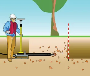
MOLING
Moling is a method, which forms the borehole by compressing the earth that immediately surrounds the compacting device which is an underground piercing (mole) is propelled by a power source. The tool is streamlined into a bullet or shape. The method is restricted to relatively small diameter lines in compressible soil conditions.
Compressed air or hydraulic fluid, transmitted to the toot through the flexible hoses, imparts energy at a blow frequency of 100 to 600 strokes per minute to a reciprocating piston located inside the nose of the tool. This action results in the tool propelling itself through the ground. It is applicable in most ground conditions from loose sand to firm clay. The method required the use of boring and receiving pit. After the operation the unit can be backed out of the borehole. The tool is removed and the cable is attached to the air hose and pulled back through the borehole. In the case of rigid pipe, it can simply be pushed through the open borehole. Any type of pipe or cable can be installed by the method.
Pipe size is generally limited to 6 inches or less. However, modern techniques in mole manufacturing have increased the ability to make the bores of large sizes. Even though 200 feet (60 meter) bores have been successfully made by this method, the span lengths were limited to 60 feet (18 meter) with 40 feet being optimum. Again span lengths have increased with modern advances in mole design.
ADVANTAGES
It is a rapid, economic, and effective method of installing small diameter lines. Any type of utility line can be installed using the method. The stability of the soil around the borehole is increased due to compaction. The investment in equipment is minimized.
DISADVANTAGES
Compaction methods are limited in their length by reliability because basic systems are unintelligent, unguided tools that tend to bury themselves, surface in the middle road or damage existing utility lines.
AUGER BORING
The auger horizontal earth boring is a process of simultaneously jacking casing through the earth while removing the spoil inside the casing by means of a rotating flight auger. The auger is a flighted tube having dual functions, firstly it has couplings at each end that transmit torque to the cutting head from the power source located in the bore pit and secondly, it serves to transfer spoil back to the machine.
AUGUR BLADES
This method requires bore pit both at the entry and exit points of the bore. The auger-boring machine consists of the boring machine, casing pipe, cutting head and augers as the major components. The power source creates the torque, which rotates the auger, which in turn rotates the cutting head. The cutting head cuts the soil and the soil is transported to the machine through the casing by means of the auger, which acts as a screw conveyor.
The pipe size that can be installed by this method ranges from 4 inches (100mm) to over 60 inches (1500 mm). However, the most common size range is 8 inches(200 mm) to 36 inches(900 mm) and the average bore length ranges between 53 meter and 68 meter, though with experience and the use of latest techniques up to 180 meter of boring is possible using auger boring.
ADVANTAGES
The major advantage is that the casing is installed at the same time as the borehole excavation takes place. This method can be used in a wide variety of soil types.
DISADVANTAGES
This method requires different sized cutting heads and auger sizes or each casing diameter, which increases the investment in equipment. The investment in bore, pit construction, and the initial setup is also required. In case of soils containing large boulders, this method cannot be used advantageously.
NEED FOR TRENCHLESS TECHNOLOGY
- The disadvantages and difficulties encountered in conventional trenching methods have resulted in thinking of the need for Trenchless Technology.
- The advantages of the no-dig technology are also responsible for the need for this technology to be adopted in mainly urban areas.
OPEN TRENCH METHOD
It is a traditional method of trenching for laying the utility lines below the surface. In present days, there are many disadvantages and difficulties in adopting this method, mainly in urban areas.
These are described below:
- As the open trench is going to create obstruction roads, busy areas, diversions have to be provided before the start of any digging.
- As the obstruction is created, the traffic has to be rerouted causing traffic jams.
- The original users of the road have to undergo hardships in the form of additional mileage as well as time.
- Many a times, while cutting deep trenches in congested areas appear in the adjacent buildings.
- Another difficulty, which is encountered very often, is the damage caused to other service lines or cables present underground, providing temporary support to these lines during the construction is a cumbersome and costly affair.
- Trenches left open overnight should be fenced and barricaded. Hand of mechanical signs should be used where necessary.
- While cutting open trenches, trees, shrubs, gardens etc. may have to be destroyed damaging the environment.
- If any rehabilitation or renovation is required, the trenches once cut and refilled should again be cut throughout and refilled causing difficulties to the public; that is, cutting and refilling is required at frequent times.
ADVANTAGES OF NO-DIG TECHNOLOGY
- It reduces damages of valuable surface.
- It reduces the danger of improperly compacted excavations.
- It saves resources.
- It is accident free.
- It avoids traffic jams.
- It makes the use of the line (track) of the old pipe possible.
- It saves underground space (pipe busting).
- It reduces the impact on the environment.
- It provides a hassle-free road surface.
- It is possible to lay service lines across the railway track, narrow lanes etc. When open trenching is impossible.
CONCLUSION
The Trenchless Technology provides a variety of benefits to the user. It combines proven sewer lining technologies, state of the art materials and the advantage to retain valuable size of sewer lines in ever-growing cities, a fact which is yet underestimated by the majority of users. To begin with, work should be undertaken for crossings under roads, national highways, railways, canals etc. and all renovations of sewerage systems in metropolitan cities. Enough know-how and technology are available to make a beginning in the field.
About the author
The author is the Managing Director at Skanda Group of Constructions. He is an experienced Civil Engineer with a demonstrated history of working in the construction industry. He is skilled in AutoCAD, Construction, Management, Concrete, and Structural Analysis.