Repair and Rehabilitating are aimed for returning degraded concrete structure it to its original state in the broad sense of the word. Modifying a structure to meet new functional or other criteria may be done using a technique established for repair and rehabilitation. Generally a structure could require rehabilitation for many reasons, such as, new functional or loading requirements requiring alterations to a structure, normal deterioration brought on by environmental effects, accident-related damage etc.
The specialist discipline of repair and rehabilitation engineering necessitates knowledge and skills that go beyond those needed for design and construction engineering. It is vital to take a methodical approach to structural deterioration, and technology management and economics should coexist in harmony. When a structure exhibits cracking, spalling, or any other evidence of deterioration, the first duty is to ascertain if the damage is structural or non-structural. The engineer in charge of rehabilitation should possess investigative, structural and material technology skills as well as knowledge of application methods.
The Repair and Rehabilitation of structures include the following:
- Techniques for inspection, evaluation, supervision, and structure maintenance Bridge fatigue problems, laboratory investigations, dynamic testing, and analysis of durable concrete.
- Seismic strengthening.
- General repairs
Structure repair and rehabilitation is the process of enhancing an existing structure to improve the likelihood that it will endure for a long time and withstand seismic effects. Base isolators, new structural elements, strengthening of current structural elements, and other methods can all be used to achieve this. The reinforced concrete structure may become structurally unsound due to concrete deterioration and corrosion of the embedded reinforcement. By fixing chloride, applying a protective coating (powder coatings based on thermosetting epoxy, polyester, or acrylic technology are electrostatic-ally sprayed) or using cathode protection, corrosion can be somewhat controlled. Once this has Happened, two alternatives of fixing the problem are to replace the structure or to strengthen it. Economically, repair and strengthening are often the only viable solution.
MATERIAL AND METHODOLOGY
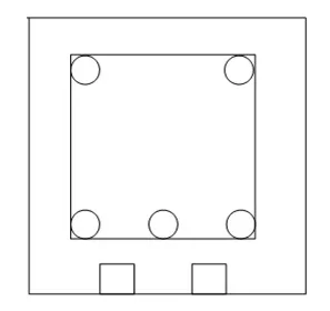
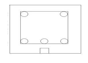
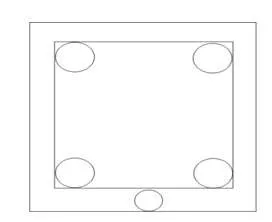
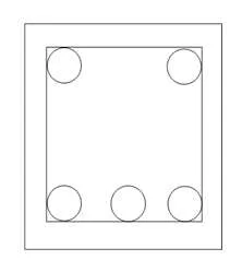
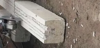
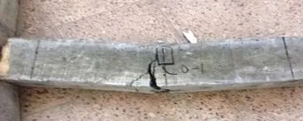
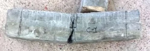
At RIMT University, an experimental study was carried out. Ten small scaled reinforced beams were examined for this experimental study using standard beams with a rectangular cross-section measuring 150x150x750 mm in size. For the initial trial testing, #3 (10mm) and #4 (13mm) Glass FRP rods were inserted into the grooves carved out of the bottom concrete surface, and the spaces were then filled with a viscous epoxy-resin paste. Three distorted 10-mm steel re-bars on the tension side, two deformed 10-mm steel re-bars on the compression side, and stirrups with a diameter of 8- mm made up the internal steel flexural reinforcement. For the first and second trial tests respectively, the retrofitted and strengthened beams were compared to a control beam, Bo-1 and Co-1. In the first test, two 10mm GFRP rods were used to reinforce the test beams B-1 and B-2. Locally accessible, the space between the concrete and the FRP rod was filled with epoxy resin. as shown in Figure 1. The cross-sectional details of the specimen beams B-3 and B-4 are shown in Figure 2 One 10 mm GFRP rod was used to reinforce the test beam B-5, as shown in Figure 3. Epoxy resin is also poured into the prepared gap between the FRP and the concrete. Only Glass FRP rods of #3 (about 10mm) were used for the second trial tests, and they were subsequently filled with cement mortar. The specimen beam C-1 underwent strengthening during the second trial tests, as depicted in Figure 4, by having a 10 mm insert positioned at the beam’s bottom surface.
In order to suggest additional repair techniques, The experiment was expanded to include the groove preparation of test beams C-2 and C-3, whose configuration differs from that of the FRP material’s installation on its near surface. As seen in Figure5, the bottom reinforcement of these beams was strengthened by inserting a 10 mm piece of cement mortar as a filler material between them. For this experiment, the concrete strength and GFRP rods used were the same for each specimen.

To replicate a true circumstance where the rods would enter the adjacent structural components, the NSM FRP rods were extended till the beam ends.
A. Material Property Concrete
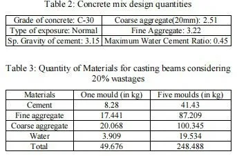
The concrete samples were taken out of the molds after the casting process had taken place for 24 hours, and they were submerged in a water tank for seven days. After that, all samples were taken out of the water curing tanks and kept in the laboratory air at a temperature of 25 C until testing began after 28 days. Three 150 mm cube-shaped concrete specimens and three 150 mm dia. by 300 mm cylindershaped concrete specimens had their compression strengths examined; the average strength of the concrete produced by the mix ratio was 33 Mpa
B. Reinforced Steel Bar
For the initial test beams, longitudinal steel reinforcing bars with a deformed, high-yield strength, 10 mm diameter, and stirrups spaced 50 mm apart, were used. Second trial beams were constructed using 8mm longitudinal steel reinforcing bars and stirrups placed 30mm apart. Each type of steel bar has three coupons that were tested. Under a uni-axial tension test, the yield strength of steel reinforcements is determined. The specimens for 8 mm steel bar had average ultimate and yield tensile strengths of 559 Mpa and 430.89 Mpa, respectively.The corresponding values for that of 10 mm are 520.09 Mpa and 369.04 Mpa.
FRP ROD Glass FRP rods with wrapped surfaces and diameters of 10 mm (#3) and 13 mm (#4) were employed to reinforce the beams’ flexural integrity. 86 mm2 and 139 mm2 are the nominal areas of #3 and #4 Glass FRP rods, respectively. The ultimate tensile strength of #3 is 1000 MPa, while its effective yield strength is #4 800 MPa, per manufacturer statistics. The FRP for the glass is 965 MPa and 772 MPa, respectively, for #4.
C. Epoxy Resin
The primary determinant is how well the epoxy glue connects the FRP to the concrete surface. determining the effectiveness of the strengthening approach. Epoxy resins come in a large variety of kinds and have a wide range of mechanical qualities.
MIX DESIGN VALUES AND PROCEDURES
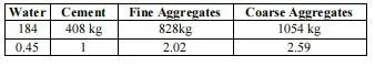
Concrete must have a 33 MPa at 28-day compressive strength to be considered solid. Ordinary Portland cement was used of 32.5grade. According to Table 1 of ACI211.1- 81(Revised 1985), the mixing water content is determined at 184 kg/m3.
Table 1: Mix Proportion
A. FLEXURAL TESTING PROCEDURES
Tests and setups
The RC beams were subjected to a center-point bending test while being spaced 590 mm apart from their supports. Using a Simple Beam with Center-Point Loading, the ASTM C293 Standard Test Method for Flexural Strength of Concrete” test method is used to assess the flexural strength of specimens that have been prepared and cured (ASTM C293). A hydraulic jack attached to an electric pump was used to apply the load, and a load cell was used to measure it. Two LVDT were installed at mid-space on both sides of the concrete beam to instrument each beam. Strain gauges are instrumented at the mid- span on the bottom face of the steel re-bar and FRP rods. The loading arrangement was the same for all of the beams. A cracking load is the weight at which the first noticeable crack appears. loading was carried out until failure.
B. PREPARATION AND CASTING OF GFRP ONTO THE BOTTOM SURFACE
When the strengthening processes were performed, the beams were in a hardened state .In order to begin installing the NSM FRP rods for the initial trial test beams, a series of grooves with specified and At the tension side of the beam sample, longitudinal holes with predetermined size were drilled into the concrete cover. Apparently, De Lorenzis used a chisel to carve these grooves. Based on the findings of bond tests with square grooves (bg=hg) and the definition of k = bg/ db, it was suggested that for round bars, k should have Smooth or lightly sandblasted bars should have a minimum value of 1.5, while deformed bars should have a minimum value of 2.0. The groove cross-section for the wrapped GFRP bars with db=13mm employed in this investigation would be bg=20mm and hg=20mm if k=1.5.
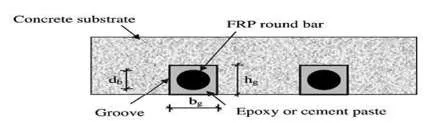
The grooves were cut using a specialized concrete saw with a diamond blade, according to the Figure 1, recommended proportions 2 .The extra sides of grooves are removed once the appropriate sides have been cut off. To remove all dirt and debris, the concrete surface is made rough using a coarse sandpaper texture. Before inserting the FRP reinforcing bars, the glue is ready and placed into the groove. In line with the manufacturer’s instructions, After being thoroughly mixed, the epoxy resin is sprayed over the grooved concrete surface.The epoxy resin is applied to the grooved concrete surface after being well mixed. After being thoroughly mixed, the epoxy resin is showered over the grooved concrete surface.The epoxy resin coating is subsequently applied to the GFRP rod. A constant, uniform pressure is applied while the epoxy is curing to ensure good contact between the epoxy, the concrete, and the GRFP rods shown in Figure 3. At room temperature, this procedure is performed.Once the epoxy resin in the groove had hardened after 24 hours, testing of the beams resumed.

As shown in below figure 4, pipes were inserted at the bottom surface of the second trial tests before casting the beams and were then pulled out to make room for the placing of FRP materials. Instead of incise, these pipes were used to compare, investigate, and demonstrate the impacts of that procedure, including tiny cracks and the wearing away of the concrete’s top layer, which weakens the concrete. The pipes for beam C-1 were put below the stirrup, which is close to the bottom surface. The stirrup, which is situated between the bottom tension reinforcement, and the pipes were erected above it. for beams C-2 and C-3. By utilizing pipes in the structural components that are vulnerable to damage, With the intention of providing room for additional repairing and rehabilitation processes, this was done in order to examine and compare the results with the first trial beams

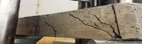
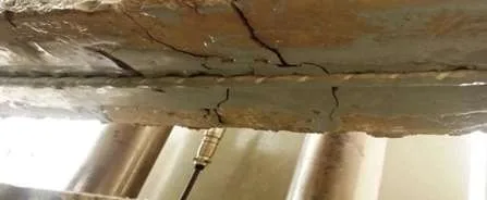
C. Analysis of the failure modes
The observed failure modes are shown in Figure 5 to 9. Flexural with steel yielding was the main form of failure for beams Bo-1, B-1, B-2, and B-5. According to Figure.3, the loss of bond (debonding) between the GFRP rod and the concrete surface occurs when the tensile steel reinforcement yields, indicating that the beam has reached its maximum level of flexural strength. Shear failure, like in the case of B-3 and B-4 beams, was the second observed mode of failure. The tension zone insertion of GFRP rod increased the reinforcing ratio for these beams. which, as shown in Figure.2, was high, causing the concrete to be compressed before the tensile reinforcement gave way, which led to the RC element failing. Flexural failure was the mode of failure for the second trial’s concrete beams, Co-1 to C-3, as shown in Figures.8 to 9.

CONCLUSION
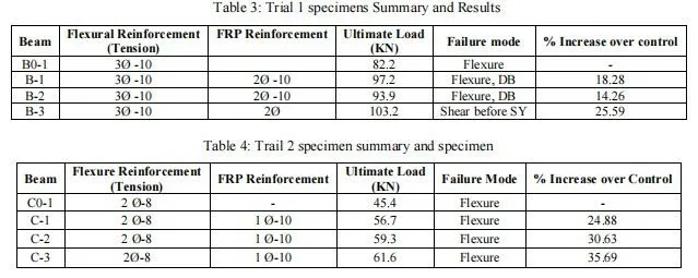
The flexural strengthening provided by NSM GFRP rods was evaluated on ten small scale reinforced concrete beams, including two control beams and seven strengthened beams. According to the test results, the strengthened beams had a greater capacity to carry the maximum load than the control beam, with increases ranging from 14.25% to 25.58% for the first trial beams and from 24.89% to 35.68% for the second trial beams. When compared to the control beam, the strengthened beams indicates an development in strength and stiffness as well as a depletion in deflection. These findings indicates that NSM GFRP rods can be used to significantly raise the flexural load carrying capacity of RC elements, indicating that this technique may be used to strengthen and repair RC beam members that have been damaged.
About the author
The author is the Managing Director at Skanda Group of Constructions. He is an experienced Civil Engineer with a demonstrated history of working in the construction industry. He is skilled in AutoCAD, Construction, Management, Concrete, and Structural Analysis.