Well detailed and constructed joints play a vital part in maintaining the integrity of the external envelope of the building, ensuring it is weatherproof and meeting any other requirements such as fire resistance and acoustic performance. This provides guidance on planning joint locations, gives requirements for joint types, widths, and the choice of sealant and discusses the fire rating of joints.
For the purpose of this, a joint is an intentional gap between adjoining elements (typically cladding) or between an element and some other portion of the structure. Joints may be horizontal, vertical or inclined. The function of a joint between precast elements is to provide physical separation between the units and, in conjunction with joint sealants, prevent the ingress of water and air into the building and if required fire resistance.
Two Aspects of Joint Selection need to be Emphasised
- The positioning of joints in relation to windows and to the structure can affect the serviceability, construction and maintenance of the building envelope. Poor joint location will lead to problems which cannot be overcome by joint detailing.
- Careful control of construction tolerances is necessary to ensure the integrity of the cladding system.
DESIGN
General Principles
It is recommended that joints be treated as a strong visual feature of architectural wall design. Recessing of joints and/or sealants will help diminish the visual impact of possible variations between adjacent surfaces.
The following general aspects need to be addressed
a. Buildability and minimum size
Select details that are simple to fabricate and install on site. Proven details should be used wherever possible.
- b. Maintenance and repair
Although modern sealants have a long service life they, if exposed to sunlight, will eventually need replacement or repair. Access for repair and replacement must be taken into consideration in the design of the building. The positioning of services or other features in front of joints will make future access difficult. Consideration must be given to the fact that inspection and repair will usually have to be made from the exterior of the building.
NUMBER, LOCATION AND WIDTH OF JOINTS
The key points are:
- For maximum economy in manufacture and erection, panels should be as large as practical.
- If architectural requirements dictate more-closely spaced joints, false joints can be used to achieve a similar visual effect.
- Weathering of the building facade can be controlled to a large extent by careful joint location.
- Recessing the sealant in the joint, or use of an open-drained system, will minimise concentrated rainwater runoff and water-stain patterns.
- A nominal joint width of 20 mm will usually be satisfactory for most conditions and is the recommended design starting point.
TYPES OF JOINTS
The most common types of joint between precast concrete cladding and/or wall panels are:
- Open-Drained Joints.
- Face-Sealed Joints.
- Compression-Seal Joints.
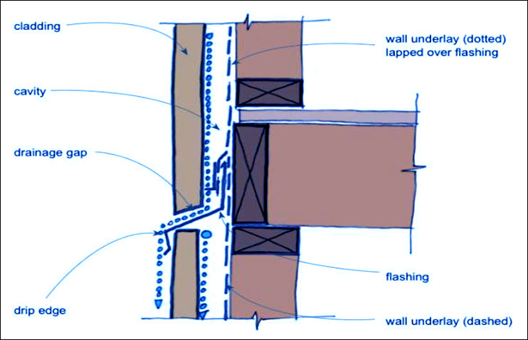
1. Open-Drained Joints
The open-drained joint is recommended for high-rise construction. It consists of a brain barrier in the form of an expansion chamber with a loose-fitting baffle and an air-seal at the interior face of the panel.
The baffle prevents direct entry of the wind-driven rainwater. The pressure in the chamber between the baffle and the internal air seal is at external air pressure. There is therefore no pressure differential to drive rain past the baffle. The air-seal is the demarcation barrier between outside and internal air pressures.
Water that enters the joint in front of the baffle is drained downwards. At every intersection between the vertical and horizontal joints, a short length of flashing (300 mm) is used to ensure water is discharged to the outside.
Advantages
- Can tolerate relatively large movements.
- The rear sealant is protected from UV light and weather.
- Can be installed from inside the building (no scaffold required).
- Long maintenance-free life.
- Best for medium- and high-rise construction.
Disadvantages
- Careful supervision is required during installation as it is difficult to remedy defects due to poor workmanship.
- Not suitable for tall vertical panels (> 9.0 m in height).
- Cannot accommodate joint gap tolerances > 5 mm.
2. Face-Sealed Joints
These joints are simple, economical and are most suited to low-rise construction. They are sealed by a single run of gun-applied sealant close to the exterior surface of the joint. A backing-rod forms the rear of the sealant. The external face seal should, where practical, be supplemented by a seal near the inside face of the panel.

Advantages
- Panel edges can have a simple profile, no grooves required.
- Can be used for complex panel shapes (angled or curved).
- Can have a rear seal as a second line of defence.
- Lowest first cost.
- Can be readily inspected, repaired or replaced.
- Best for low-rise construction.
Disadvantages
- Must be applied from external scaffolding or other forms of access.
- Sealant is exposed to UV light and weather – needs more maintenance.
- In a single-seal system even a small failure may allow water penetration due to capillary effects and pressure differentials.
3. Compression-Seal Joints
This type of joint utilises a compressible impregnated polyethylene or polyurethane foam strip. The strip is pre-compressed and inserted into the joint after the panels are erected or it is glued in position before placement of the second panel. It then expands to fill the joint. The use of this type of joint seal is usually limited to low-rise buildings such as factories and warehouses where wind pressures are low. It can be used where spandrel beams, downturns or columns restrict the access required for placement of gun-applied sealants.

Advantages
- Simple and quick to install.
- Panel edges can be plain or simple profiles.
- Economical.
Disadvantages
- Cannot be fully weatherproof, so limited to low-rise industrial buildings.
- Joint width is critical.
- Maintaining compression on the seal at the intersection of horizontal and vertical joints is difficult.
- Difficult to maintain and/or replace.
- Time-consuming while erecting.
JOINT SEALANTS
The choice of sealant and its specification should be discussed with sealant manufacturers. Factors to be considered by the designer when choosing a suitable sealant material include:
- The sealant should be impermeable to water.
- It should have a low elastic modulus to accommodate strain due to joint movement without significant stress, with the shape of the sealant influencing the stress in the sealant.
- It should be able to recover its original shape after cyclic deformation.
- It must bond firmly to the joint face without failing in adhesion nor splitting or peeling under the anticipated joint movements.
- It must not soften or flow at higher service temperatures and should not harden and become brittle at low temperatures.
- It should not be adversely affected by ageing or weathering and should be stable when exposed to UV light.
- For face-sealed joints the sealant should have a stable colour, be non-staining and resistant to pickup of dirt.
Sealant Types
Field-moulded sealants are available in the following types:
- Polysulphide sealants
- Polyurethane sealants
- Acrylic sealants
- Butyl sealants
- Silicone sealants.
Note, silicone sealants should be avoided where possible as they stain the concrete surface and cannot be painted.
Joint Design and Sealant Application
To ensure the joint and sealant give satisfactory performance, the following points should be noted:
- Correct Joint Preparation.
- Correct Sealant-Backing Systems.
- Correct Joint Geometry.
- Sufficient Curing Time.
Fire Rating of Joints
External cladding may be required to have a specified Fire Resistance Level (FRL). Cladding panels will usually be designed or tested to meet these requirements in accordance with Section 5 of AS 3600.
Most sealant manufacturers produce sealants that are designed to provide resistance to fire. The joint details and sealants should be designed and applied in accordance with the manufacturer’s recommendations to give the required level of fire resistance.
CONCLUSION
- The connection generally comprises one or more joints (compression/shear/tension joints).
- There are well established methods to design the joints for the subjected forces.
- The choice of joints depends upon the stress levels at serviceability/ultimate stage in addition to fire, impact, accidental loads etc.
- The alternate load path shall be available in case of failure of one joint.