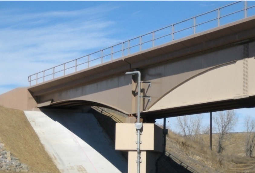
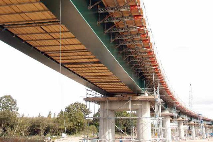
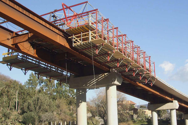
Steel-concrete composite bridges are used as an alternative to concrete bridges because of their ability to adapt their geometry to design constraints and the possibility of reusing some of the materials in the structure. Steel Composite bridge decks usually consist of a steel structure that works together with a top concrete slab, which forms the road, rail, or pedestrian platform. This structural solution has been adopted over the last 50 years in small span bridges, as well as in medium and long-span bridges.
Mechanical connectors used in the steel-concrete composite structure can be divided into two major types. The first one includes discrete connectors which are usually located along the girder. Each of these connectors was shop-welded for instance to the upper flange of the steel beam and after that got embedded in concrete on site. The other type includes continuous types of shear connectors – group of members, formed in one piece, which were assumed to act as a continuous shearing medium along the beam.
What does bridge composite mean?
‘Composite’ means that the steel structure of a bridge is fixed to the concrete structure of the deck so that the steel and concrete act together, thus reducing deflections and increasing strength. This is done using ‘shear connectors’ fixed to the steel beams and then embedded in the concrete. Shear connectors can be welded on, perhaps using a ‘stud welder’, or better still on export work, by fixing nuts and bolts.

Shear connectors, correctly spaced to resist the loads, make the concrete work ‘compositely’ with the steel. Usually, the steel carries its own weight and that of the wet concrete. But when the concrete is ‘cured’ and has acquired its full strength, then all future loads (traffic, surfacing, wind, water, pressure, seismic loads) are shared by the steel/concrete composite.
The concrete is good in compression, while the steel is good in tension and compression. This composite bridge design can be used in the following ways:
- Simple Beam Bridges – On short spans (8m, 10m, 15m and then more expensively up to 24m), bridges can be made from several beams under the roadway straight across the gap. The bridges benefit the most from composite action.
- Over Truss Bridges – These are similar to simple beam bridges but for longer spans, from say 18m up to approx 100m. The deck is still on top of the steel structure, so goes into compression when deflected.
- Transoms on any type of bridge – Transoms go from side to side across a bridge and carry the deck loads to strong steel frames on either side. This is usually on ‘open top’ through truss bridges or ‘closed-top’ through truss bridges.
- Decking – In a normal steel building the concrete can act together with steel decking, the steel decking taking the place of the regular steel reinforcing bars within the concrete. However in a bridge, the underside of the decking is liable to corrode over time, so is not counted as part of the reinforcement. It is just used as ‘lost formwork’.
Advantages of steel-concrete composite bridges
The construction process of the SCCB is unique because the construction has a differentiation between the steel and concrete parts of the structure. The most common process is to build and place the steel part first using support systems to reduce the deflections of the steel part of the bridge. Then, the concrete slab formwork and the reinforcement are placed and the concrete is poured. This unique procedure gives the structure a characteristic behavior and researchers are currently developing and studying different construction processes for SCCBs. The construction processes can be summarized as continuous precast girder bridges, incremental launching, span-by-span construction, and cantilever construction.
To achieve the objectives of the current design, steel-concrete composite bridges (SCCBs) can be a good alternative due to the recyclability of the steel parts of the structure. SCCBs have been used extensively since the 20th century when composite structure theories were developed more generally.

In the substructure to the superstructure framework corner region of integral bridges, there is sufficient material available to accommodate the compressive forces without the introduction of additional plates into the concrete. During construction, the endplate detail caters to sufficient bearing capacity to place the prefabricated girders close to the support faces.
It is possible to influence the load carried by a composite deck section in several ways during the erection of a bridge. By propping the steel beams while the deck slab is cast and until it has gained strength, then the composite section can be considered to take the whole of the dead load. This method appears attractive but is seldom used since propping can be difficult and usually costly.
With continuous spans, the concrete slab will crack in the hogging regions and only the steel reinforcement will be effective in the flexural resistance unless the concrete is prestressed. Generally, the concrete deck is 220mm to 250mm thick with beams or plate girders between 2.5m and 3.5m spacing and depths between span/20 and span/30.
Composite action is developed by the transfer of horizontal shear forces between the concrete deck and steel via shear studs which are welded to the steel girder. Typical types of connectors are shown below, the stud connector being the most commonly used.
Composite bridges are more and more popular around the world since they combine some advantages of steel bridges with some key factors of concrete bridges. In fact, a composite bridge presents the following:
- A steel main structure that is much easier to erect if compared to the construction of a concrete girder
- A light structure, which imposes smaller loads on piers and foundations, allowing for economy
- A concrete slab, which is cheaper and easier to build than a steel orthotropic deck, and also presents two other advantages:
- A higher mass, which induces fewer vibrations, noise, and dynamic loads on the supporting structure
- A top surface that allows for easy paving with traditional methods, while weak points of the orthotropic deck consist of the difficulty of realizing a strong binding, the delicate execution, and some concern about the durability of its paving
Steel-concrete composite structures have been used in construction to benefit from the elements’ best material behavior. The interaction between the two materials and how to provide the most effective connection has seen multiple approaches.

Conclusion
Composite steel-concrete decks are particularly well designed to work in mid-span regions. The top concrete slab withstands the compressive forces while the bottom steel structure copes with the tensile forces generated by the positive bending moments. However, these composite decks are less efficient for the negative bending moments over the intermediate support cross-sections. On one hand, the slab of concrete tends to crack under the tensile forces, and significant quantities of reinforcing are needed to control this effect. On the other hand, the steel structure below needs stiffeners to ensure its high resistance to compression, without local or global instability. Decks with double composite action are a recent development in this structural solution, in which the second slab of concrete is added to the bottom flange of the steel structure.


