The bearing capacity of foundations is needed for dimensioning the foundation for any structure. The safe bearing capacity may be defined as the “Maximum intensity of loading that the foundation will safely carry without the risk of shear failure of soil irrespective of any settlement that may occur”.
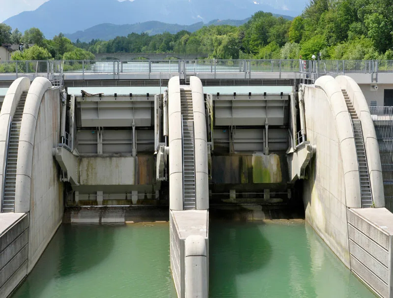
The bearing capacity of the underlying strata is required for the design of the foundation of the Barrage/Weir. Keeping this in view, National Institute of Rock Mechanics (NIRM) Karnataka, conducted Plate load test at the barrage/weir axis at one of the Hydroelectric projects as per IS: 1888-1982 (Reaffirmed 2002) “Method of load test on soils”.
The methodology, investigation procedure, analysis of the data is given in different chapters in this paper. The conclusion illustrates the ultimate bearing capacity determined by plate load test at the proposed barrage axis no.3 ranges between 60.17 to 75.02 T/m2.
2.0 METHODOLOGY
Determination of bearing capacity of underlying strata by Plate load test. Method/Procedure: As per IS: 1888-1982 (Reaffirmed 2002) standard, “Method of load test on soils” for plate load test.
3.0 GEOLOGY
The project area consists of quartzo feldsphathic gneiss, biotite gneiss with bands of quartzite and schist which are dissected by quartz veins and occasional pegmatite intrusions belonging to Surrey Formation of Thimphu Group of rocks. Generally, the rock is traversed by four to five sets of discontinuities with rock trending SE to E dipping 10- 45º.
4.0 DETERMINATION OF ULTIMATE/SAFE BEARING CAPACITY
The knowledge of behaviour of soil (or) any foundation material upon loading can be studied in-situ by carrying out plate load test. The ultimate bearing capacity and safe bearing capacity are essential for the design of foundations.
4.1. Theory
Settlement of footing, St is given by the following relationship:
St = Sp(B(Bp + 0.3)|Bp(B + 0.3)2
Where,
St = Settlement of foundation in m
Sp = Settlement of test plate in m
B = Size of the footing in m, and
Bp= size of the test plate in m
Corresponding to settlement of plate, the allowable bearing capacity is calculated from the plot of load intensity versus settlement of plate.
4.2 Description of the test area
The plate load tests are carried out at the proposed barrage site, Axis no. 3. The test area falls in the downstream of Axis no.3 to the right bank (Figure 4.1)
Table 4.1 Details of the test locations
| Point Id | Easting | Northing | Elevation (m) |
| PLT1 | 49716.829 | 58968.506 | 1174.811 |
| PLT2 | 49724.084 | 58943.717 | 1174.704 |
| PLT3 | 49715.053 | 58917.203 | 1174.521 |
| PLT4 | 49723.593 | 58916.312 | 1174.557 |
Figure 4.1 Plate load test locations
4.3 Site preparation
An area of size around 14 x 14 m is excavated to a depth of 2 m from the existing riverbed level to reach the test level. Later, a test pit (Figure 4.2) of size 3.0 x 3.0 x 1.5 m (L x W x D) is excavated manually in the middle of the earlier excavated area. Finally, the test pit is leveled.
4.4 Equipment and installation
4.4.1 Installation of reaction load
The design load intensity is 50 T/m2. With a factor of safety 2 the load intensity is increased to 100 T/m2and the corresponding maximum load calculates to 56.25 T for a test plate of size
0.75 x 0.75 m.
The reaction load provided comprises of a composite girder platform of size and weight 8.7 x 4 m (L x B) ,11.84 T respectively and plates of 40 nos. each weighing 2 T (Figure 4.3). The counter load setup is simply supported on a set of three ISMB 600 x 210 mm girders of length 8.0 m placed on either side of the test pit at 3.5 m from the pit centre.
The ISMB 600 x 210 girders of length 8.0 m are placed on the sandbags and levelled. Secondly, the composite girder is placed on the ISMB girders. It is ensured that the test pit and composite girder platform are concentric and co-planar to each other. Finally, the plates are arranged carefully so that the load is distributed uniformly over the composite girder platform.
Figure 4.2 Test pit
Figure 4.3 Reaction load arrangement
4.4.2 Installation plate load equipment
The plate loading equipment comprises of bearing plate, load distribution plates, extension columns and hydraulic cylinders, pump, and hoses. Complete set up of the plate load equipment is shown in Figure 4.4 (a).
A 25 mm thick bearing plate of size 750 mm X 750 mm is placed over a layer of sand of thickness between 3-5 mm. The bearing plate is leveled co-axial with the reaction setup. Three hydraulic cylinders of each 100 tons capacity are placed above the jack base plate. The extension columns along with stiffeners are placed one above the other up to the girder leaving enough space to accommodate a load distribution plate. The hydraulic cylinders are connected to the hydraulic pump through the manifold.
4.4.3 Installation of displacement measurement module
The module consists of datum bar assembly (Figure 4.4 (b)) and LVDTs (Linear Variable Displacement Transducer). The settlement of the river-bed material (RBM) is measured using LVDTs (Figure 4.5 (a)) which has a least count of 0.01 mm. Four LVDTs are mounted to the datum bars placed at the four corners of the bearing plate. The supports of the datum bar assembly are placed on the leveled firm ground away from the loading area.
4.4.4 Data acquisition system
The data acquisition system comprises of a high resolution and high accuracy data logger (Figure 4.5 (b)) connected to the laptop.
i) PICO 24-bit high resolution data logger, (PICO Technology Ltd.) to log the settlement and pressure.
ii) The data logger is connected to a laptop to monitor and record the data.
Figure 4.4 (a) Plate load equipment (b) Datum bar assembly
Figure 4.5 (a) LVDT (b) Data logger
4.5 Test procedure
The test was conducted by applying vertical pressure at the bottom and recording settlement of the bearing plate. The load intensity increments are given in accordance to IS: 1888- 2002 as given in Table 4.2.
Table 4.2. Load increment calculations
| A | 1 kg/cm2on plate (14.07 kg/cm2in pressure transducer) in cumulative equal increments |
| B | Total load intensity on plate / estimated ultimate bearing capacity = 100 T/ m2or 10 kg/cm2. So, 1/5th of Total load intensity on plate = 2.0 kg/cm2 (28.14 kg/cm2in pressure transducer) |
| Here A < B, Therefore, the load intensity of 14.07 + 3 kg/cm2in pressure transducer as given in ‘A’ should be applied in cumulative equal increments. |
The load is applied without impact, fluctuation, or eccentricity. The pressure and settlement readings are logged for every second in the laptop through a high resolution data acquisition (Pico, ADC-24 bit) system.
Initially, a seating load/static load of 0.07 T/m2is applied for about 10 minutes to hold the plate in position and later, the pressure is released. The settlement if any is logged for each second till the rate of rebound is negligible. Further the test is continued as described below-
(i) The pressure is raised gradually at a constant rate to 14.0 kg/cm2(load intensity of 10 T/m2on the soil strata) and was maintained till the rate of settlement was constant or reduced to 0.02 mm/min.
(ii) After the settlement was constant, pressure was raised to the next increment of 28.0 kg/cm2(load intensity of 20 T/m2). It was maintained till the rate of settlement was constant or reduced to 0.02 mm/min.
(iii) The pressure was increased to 42 kg/cm2(load intensity of 30 T/m2), and was maintained till the rate of settlement was constant or reduced to 0.02 mm/min. (iv) The investigation is continued till one of the following is achieved. • settlement of a bearing plate of 25 mm.
• failure occurs (or) estimated ultimate bearing capacity of 100 T/m2. 4.6 Results
The load intensity and settlement data for PLT-1,2,3 & 4 are given in the Table 4.3 to 4.6. The settlement and load intensity are both plotted to logarithmic scale. It results in two straight lines and the intersection of this indicates the yield point or the ultimate bearing capacity of the underlying strata. The settlement versus load intensity plots is given in Appendix-A. The ultimate bearing capacity (UBC) and total settlement obtained for the four test locations from the above plots is given in Table 4.7.
Table 4.3 Load intensity and settlement of PLT-1
| Location | Load intensity on plate T/m2 | LVDT 1 | LVDT 2 | LVDT 3 | LVDT 4 | Cumulative settlement of plate mm |
| Axis-3 Right bank | 1.10 | 0.12 | 0.1 | 0.1 | 0.09 | 0.10 |
| 10.00 | 0.49 | 0.48 | 0.54 | 0.50 | 0.50 | |
| 20.05 | 0.97 | 0.98 | 0.86 | 0.99 | 0.95 | |
| 30.00 | 1.37 | 1.27 | 1.29 | 1.39 | 1.33 | |
| 40.11 | 1.71 | 1.73 | 1.69 | 1.67 | 1.70 | |
| 50.00 | 1.99 | 2.30 | 2.12 | 2.43 | 2.21 | |
| 60.17 | 2.71 | 2.83 | 2.61 | 2.73 | 2.72 | |
| 70.00 | 4.29 | 4.31 | 4.49 | 4.39 | 4.37 | |
| 80.02 | 5.91 | 6.13 | 6.01 | 5.99 | 6.01 | |
| 90.00 | 7.98 | 7.99 | 8.09 | 7.86 | 7.98 | |
| 100.40 | 10.05 | 10.03 | 9.63 | 10.09 | 9.95 |
Table 4.4 Load intensity and settlement of PLT-2
| Location | Load intensity on plate T/m2 | LVDT 1 | LVDT 2 | LVDT 3 | LVDT 4 | Cumulative settlement of plate mm |
| Axis-3 Right bank | 1.05 | 0.01 | 0.02 | 0.01 | 0.01 | 0.01 |
| 10.00 | 0.31 | 0.21 | 0.25 | 0.15 | 0.23 | |
| 20.05 | 0.60 | 0.58 | 0.89 | 0.37 | 0.61 | |
| 30.00 | 1.11 | 0.92 | 1.09 | 0.81 | 0.98 | |
| 40.11 | 1.37 | 1.38 | 1.26 | 1.39 | 1.35 | |
| 50.00 | 1.59 | 1.75 | 1.57 | 1.77 | 1.67 | |
| 60.17 | 1.94 | 1.97 | 2.09 | 1.96 | 1.99 | |
| 70.00 | 2.49 | 2.32 | 2.55 | 2.36 | 2.43 | |
| 80.02 | 5.05 | 5.21 | 5.05 | 4.61 | 4.98 | |
| 90.00 | 8.81 | 8.61 | 8.89 | 7.70 | 8.50 | |
| 100.40 | 13.36 | 13.26 | 13.25 | 12.21 | 13.02 |
Table 4.5 Load intensity and settlement of PLT-3
| Location | Load intensity on plate T/m2 | LVDT 1 | LVDT 2 | LVDT 3 | LVDT 4 | Cumulative settlement of plate mm |
| Axis-3 Right bank | 1.20 | 0.01 | 0.02 | 0.01 | 0.01 | 0.01 |
| 10.00 | 0.10 | 0.21 | 0.16 | 0.09 | 0.14 | |
| 20.00 | 0.47 | 0.33 | 0.52 | 0.21 | 0.38 | |
| 30.00 | 0.64 | 0.58 | 0.89 | 0.40 | 0.63 | |
| 40.00 | 0.88 | 0.77 | 1.00 | 0.69 | 0.84 | |
| 50.00 | 1.17 | 1.02 | 1.23 | 0.79 | 1.05 | |
| 60.00 | 1.28 | 1.16 | 1.40 | 1.31 | 1.29 | |
| 70.00 | 2.05 | 1.91 | 2.26 | 1.83 | 2.01 | |
| 80.00 | 6.05 | 3.80 | 4.45 | 3.91 | 4.55 | |
| 90.00 | 9.25 | 7.09 | 8.51 | 7.51 | 8.09 | |
| 100.40 | 13.21 | 11.95 | 13.00 | 12.98 | 12.79 |
Table 4.6 Load intensity and settlement of PLT-4
| Location | Load intensity on plate T/m2 | LVDT 1 | LVDT 2 | LVDT 3 | LVDT 4 | Cumulative settlement of plate mm |
| Axis-3 Right bank | 1.05 | 0.12 | 0.08 | 0.13 | 0.07 | 0.10 |
| 10.00 | 0.70 | 0.58 | 0.95 | 0.40 | 0.66 | |
| 20.00 | 1.28 | 1.16 | 1.44 | 1.01 | 1.22 | |
| 30.00 | 1.75 | 1.48 | 1.86 | 1.39 | 1.62 | |
| 40.00 | 2.05 | 1.91 | 2.26 | 1.83 | 2.01 | |
| 50.00 | 2.52 | 2.29 | 2.85 | 2.37 | 2.51 | |
| 60.00 | 3.02 | 2.60 | 3.63 | 2.81 | 3.01 | |
| 70.00 | 6.00 | 4.55 | 6.17 | 5.13 | 5.46 | |
| 80.00 | 8.20 | 6.23 | 8.77 | 7.51 | 7.90 | |
| 90.00 | 10.91 | 11.20 | 10.60 | 9.95 | 10.70 | |
| 100.20 | 14.15 | 13.75 | 13.16 | 12.95 | 13.50 |
Table 4.7 Ultimate bearing capacity by plate load test
| Test No. | Total settlement mm | UBC T/m2 | Corresponding settlement mm |
| PLT-1 | 9.95 | 60.17 | 2.72 |
| PLT-2 | 13.02 | 75.02 | 2.88 |
| PLT-3 | 12.79 | 70.33 | 2.01 |
| PLT-4 | 13.50 | 65.02 | 3.24 |
5.0 CONCLUSIONS
i) The ultimate bearing capacity determined by plate load test at the proposed barrage axis no.3 ranges between 60.17 to 75.02 T/m2.
ii) The estimated ultimate bearing capacity of 100 T/m2is obtained prior to the permissible settlement of 25 mm.
REFERENCES
1. IS: 1888-1982 (Reaffirmed 2002) standard, “Method of load test on soils” 2. Internal reports and communications.
About the author
Dr. DS Subrahmanyam is the Head of the department for Geotechnical Engineering Division, National Institute of Rock Mechanics. He is associated mainly with the geological and geotechnical studies of many important engineering projects in the Himalayan region and presently responsible for planning, programming, implementation and monitoring of engineering geological/geotechnical investigations of hydropower projects, communication projects, underground storage plants, underground mines and irrigation projects in India and abroad. He established an innovative technique for conducting stress measurements in fractured and porous rocks for which he is going to get the Patent rights from Controller General, Patents & Designs (India). He is credited with preparing the Stress Map of India for contribution to the World Stress Map.
He has authored more than 60 papers to his credit, published in National and International journals and proceedings and nearly 120 Technical reports and 5 Research projects submitted for various assignments. He is also the Fellow and life member for various National and International societies and associations. He is also an Editor for 7 International journals and Reviewer for various National and International Magazines. He visited Finland, Sweden, Singapore, Bhutan and Nepal in connection with the Project related works and seminars.


