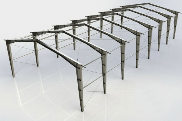
Structural loads in pre-engineered buildings are an important consideration in the design of buildings. Building codes require that structures be designed and built to safely resist all actions that they are likely to face during their service life, while remaining fit for use. Minimum loads or actions are specified in these building codes for types of structures, geographic locations, usage and building materials. Structural loads or actions are forces, deformations, or accelerations applied to structure components. Loads cause stresses, deformations, and displacements in structures. Assessment of their effects is carried out by the methods of structural analysis. Excess load or overloading may cause structural failure, and hence such possibility should be either considered in the design or strictly controlled.
Forces that act vertically are gravity loads like dead load, collateral load, live load. Forces that act horizontally, such as stability, wind and seismic events require lateral load resisting systems to be built into structures. As lateral loads are applied to a structure, horizontal diaphragms transfer the load to the lateral load resisting system. The loads combinations include different combinations according to standard codes (IS 800 – 2007 and AISC -89/ MBMA – 2002) by considering both serviceability and strength criteria. Given below are different types of structural load in pre-engineered buildings.. .
Different types Structural loads in pre-engineered buildings
Dead load
Dead loads, also known as permanent or static loads, are those that remain relatively constant over time and comprise, for example, the weight of a building’s structural elements, such as beams, walls, roof and structural flooring components. Dead loads may also include permanent non-structural partitions, immovable fixtures and even built-in cupboards.
Dead load on a PEB structure is the result of the weight of the permanent components such as beams, floor slabs, columns and walls. These components will produce the same constant ‘dead’ load during the lifespan of the building. Dead loads are exerted in the vertical plane. Dead load is calculated According to IS: 875 (Part 1) –1987. Dead load = volume of member x unit weight of materials. By calculating the volume of each member and multiplying by the unit weight of the materials from which it is composed, an accurate dead load can be determined for each component. The different components can then be added together to determine the dead load for the entire structure.

Collateral load
Collateral load is a subset of dead load that includes the weight of any materials other than permanent construction. These materials can include pipes, sprinklers, mechanical ducts, electrical conduits, ceilings, and finishes. Some typical weights of these components include sprinklers, lights, and mechanical ducts etc. Collateral loads are added dead loads hung from the building system, or any interior weight of permanent materials other than the actual metal building system. Electrical systems hanging from the ceiling, or an internal sprinkler system are both in the collateral load category. Collateral load is an additional weight that generates from additional permanent materials rather than the structural system, for instance, ceilings, lighting, mechanical shafts and mechanical ducting system. Typical values range from 0.1 to 0.3 kN/m2.
Live load
Live loads refer to the dynamic forces from occupancy and intended use. They represent the transient forces that can be moved through the building or act on any particular structural element. Also measured in psf, these loads include the anticipated weight of people, furniture, appliances, automobiles, moveable equipment and the like. Because live loads depend on structural strength, knowledge of the exact planned use of the building is critical. The might of the dead load, or lack thereof, often defines how much live load it can handle. Reinforced concrete creates the heaviest dead loads but also supports the most weight with its tremendous compressive strength. Structural steel offers much less of a dead load and provides superior support for live loads in multi-story buildings. Natural and engineered wood rest relatively lightly on the foundation but support less live loads than steel and concrete. Live load acting on structural members is due to the moveable equipment and stuff. For pre-engineered buildings, live load is generated on the roof during construction and maintenance work. The corresponding code used for calculating life load is ASCE/SEI 7-10.

Wind load
Wind load is the load, in pounds per square foot, placed on the exterior of a structure by wind. This will depend on the angle at which the wind strikes the structure and the shape of the structure.
Preventing wind damage involves strengthening areas where buildings could come apart. The walls, roof and foundation must be strong, and the attachments between them must be strong and secure. For a structure to wind loads, it must have a continuous load path from the roof to the foundation — connections that tie all structural parts together and can resist types of wind loads that could push and pull on the building in a storm. Wind loads are governed by wind speed, roof slope, eave height, exposure category and open wall conditions of the building. Usually, steel buildings are not designed for a wind speed less than 110 km/h. Wind exerts three types of forces on a structure namely Uplift load [Wind flow pressures that create a strong lifting effect, much like the effect on airplane wings], Shear load [Horizontal wind pressure that could cause racking of walls, making a building tilt] and Lateral load [ Horizontal pushing and pulling pressure on walls that could make a structure slide off the foundation or overturn].

Seismic load
Seismic loads are produced by the structure’s resistance to motion (or inertia), when the ground accelerates during an earthquake. The magnitude of seismic loads depends on many factors, some of which are functions of the location of the building and nature of the site. Furthermore, many of these factors vary greatly from site to site in the same general area. s. PEB manufacturers can help to achieve this by combining steel structures with concrete for optimal protection from the earthquake. They know from experience how much of concrete should be replaced with metal frames and what type of steel to use in a specific earthquake prone zone. More importantly, metal sections, the mainstay of PEB engineering have higher resistance to earth-quake damages than an only-concrete building.


