Bridge deck erection refers to the process of installing the bridge deck, which is the upper surface of a bridge that carries the traffic load. It involves lifting and placing the precast concrete segments or steel girders that form the bridge deck onto the supporting structures, such as piers or abutments.
The bridge deck erection process typically follows the construction of the bridge substructure, including the piers, abutments, and other supporting elements. Once the substructure is complete, the bridge deck components are lifted and positioned in their designated locations.
During the bridge deck erection process, it is essential to ensure proper alignment, levelness, and secure connection of the components to maintain the structural integrity of the bridge. Safety measures, such as temporary supports and stability systems, are employed to prevent accidents and maintain stability during the erection process. Bridge deck erection is a critical phase in bridge construction, as it brings the bridge closer to its final form and enables the subsequent installation of additional components, such as barriers, wearing surfaces, and utilities, to complete the bridge structure.
The process of Bridge deck erection
The bridge deck erection process typically involves the following steps:
1. Preparation: Mobilize necessary equipments and verify that all required materials, such as precast concrete segments or formwork, are available and in proper condition for deck placement.
2. Deck Element Placement: The bridge deck elements, which can be precast concrete panels, steel sections, or cast-in-place concrete, are positioned and placed onto the substructure.
3. Alignment and Connection: The deck elements are aligned and adjusted to ensure proper alignment, levels, and smooth transitions.
4. Reinforcement and Formwork: If the bridge deck is cast-in-place concrete, reinforcement steel, such as rebar or post-tensioning cables, is placed according to the design specifications. Temporary formwork is also installed to contain the concrete during pouring and curing.
5. Concrete Placement and Finishing: The concrete is poured into the formwork, ensuring proper consolidation and compaction. Concrete finishing techniques, such as screeding, floating, and troweling, are applied to achieve the desired surface texture and level.
6. Curing and Protection: The freshly placed concrete is allowed to cure and gain strength over time. Measures may be taken to protect the curing concrete from adverse weather conditions or excessive drying, such as covering it with curing blankets or applying curing compounds.
7. Joint and Expansion Systems: Expansion joints or other joint systems are installed on the bridge deck to accommodate thermal expansion and contraction and provide flexibility.
8. Surface Treatments: After the bridge deck has cured, surface treatments such as waterproofing membranes, anti-skid coatings, or wearing surfaces may be applied to enhance durability, aesthetics, and functionality.
Bridge deck erection requires careful planning, coordination, and adherence to engineering specifications. It often involves specialized equipment, skilled labor, and attention to safety protocols. The method of bridge deck erection can vary depending on factors such as the bridge design, material, and site conditions.

Bridge Deck Erection Methods
There are several methods used for bridge deck erection, depending on the design, materials, site conditions, and project requirements. Here are some commonly used bridge deck erection methods:
1. Precast Segmental Erection: In this method, the bridge deck is precast into segments off-site and transported to the construction site. The segments are lifted and placed onto the bridge substructure using cranes, gantries, or other specialized lifting equipment. The segments are then connected and post-tensioned to form a continuous deck. Precast segmental erection is often used for longer-span bridges and allows for efficient construction and faster completion.
2. Cast-in-Place Concrete Erection: In this method, the bridge deck is constructed on-site by pouring and curing concrete directly onto the bridge substructure. Temporary formwork is used to shape the deck, and reinforcement steel is placed according to design specifications. Concrete pumps and placement equipment are used to efficiently distribute and place the concrete. Cast-in-place concrete erection is suitable for shorter-span bridges or where complex geometries or detailing is required.
3. Incremental Launching: Incremental launching, also known as free cantilever or balanced cantilever construction, is a method used for continuous bridge decks. The deck is constructed segment by segment, starting from one abutment or pier and extending outwards. Specialized launching gantries or trusses are used to support and move the deck segments into place. The segments are typically post-tensioned or connected using external tendons or temporary support cables. Incremental launching allows for continuous deck construction without the need for intermediate temporary supports.
4. Steel Girder Erection: For steel girder bridges, the deck is erected by placing and connecting steel girders onto the bridge substructure. The girders are lifted and positioned using cranes or gantries and are then connected and secured to form the deck. Steel girder erection allows for efficient and rapid deck construction, particularly for shorter-span bridges.
5. Movable Scaffolding Systems: Movable scaffolding systems (MSS) are specialized platforms or formwork systems that move along the length of the bridge to facilitate deck construction. MSS are typically used for cast-in-place concrete decks. They provide a stable working platform and formwork, allowing for continuous pouring and construction of the bridge deck. MSS can be adjusted and moved incrementally to accommodate the construction progress.
6. Pre-stressed Concrete Beam Erection: In this method, pre-stressed concrete beams are used to form the bridge deck. The beams are precast off-site and transported to the construction site. They are then lifted and placed onto the bridge substructure using cranes or gantries. The beams are connected and post-tensioned to form the deck. Pre-stressed concrete beam erection is often used for medium to long-span bridges and allows for efficient construction and improved durability.
These are some of the commonly used bridge deck erection methods. The selection of the method depends on factors such as bridge design, span length, site conditions, available equipment, and project constraints.
Different types Bridge Deck Erection Equipments
Launching girder
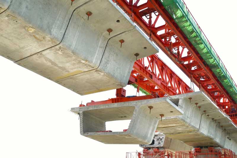
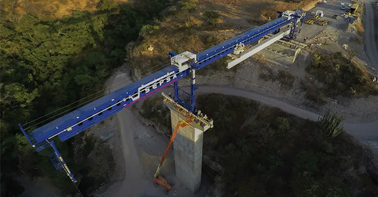
A launching girder, also known as a bridge girder erection machine or simply a girder launcher, is a specialized piece of equipment used for the construction of bridge decks. It is specifically designed to lift, transport, and place precast concrete or steel girders onto bridge piers or abutments, forming the superstructure of the bridge.
A launching girder typically consists of a steel truss structure, which provides strength and stability during the erection process. The truss spans the length of the bridge and is supported by temporary piers or falsework. The launching girder is equipped with lifting mechanisms, such as hydraulic jacks or strand jacks, that provide the necessary force to lift the precast girders. These mechanisms ensure controlled and precise lifting during the erection process.
The launching girder is capable of moving along the bridge alignment to transport the precast girders to their designated locations. It can traverse on rails or a self-propelled system that allows for accurate placement of the girders.
Once the launching girder is in position, the lifting mechanisms are engaged to lift the precast girders. The girder is then transported to the appropriate location and placed onto the bridge piers or abutments, aligning it with the adjacent girders.The launching girder employs an incremental launching method, where each girder is placed and connected to the previously installed girder. The girder launcher then moves forward incrementally, allowing for the continuous placement of girders until the entire bridge deck is formed.
Gantry cranes
Gantry cranes are commonly used for bridge deck erection due to their versatility and ability to handle heavy loads. They are often utilized in bridge construction projects where longer spans or multiple spans need to be erected simultaneously. Gantry cranes consist of a steel or aluminum framework that spans the bridge piers or abutments. The framework is typically supported by wheels or tracks, allowing the crane to move horizontally along the bridge’s length. Gantry cranes are available in various configurations, including single-girder or double-girder designs, depending on the specific project requirements.
Gantry cranes are designed to handle significant lifting capacities, making them suitable for transporting and placing heavy bridge deck segments. The lifting capacity of gantry cranes can range from a few tons to several hundred tons, depending on the crane’s size and configuration. Gantry cranes are used to lift precast bridge deck segments from a staging area and transport them to the precise location on the bridge piers or abutments. The crane’s horizontal movement capability allows for accurate positioning of the segments along the bridge alignment. Gantry cranes can be customized and adapted to fit different bridge configurations and construction methods. They can be equipped with various lifting attachments, such as hooks or clamps, to securely grip and handle different types of bridge deck segments, including precast concrete or steel girders.

Floating cranes
Floating cranes are specialized cranes that are mounted on barges or pontoons and used for bridge construction projects near water bodies. They are particularly suitable for bridge deck erection over rivers, lakes, or coastal areas where access from the land is limited or challenging.
Floating cranes are mounted on barges or pontoons, providing stability and mobility on water bodies. The crane is secured to the barge or pontoon to ensure safe and controlled lifting operations during bridge deck construction. Floating cranes are designed to handle significant lifting capacities, ranging from a few tons to several hundred tons. The lifting capacity depends on the specific size and configuration of the floating crane.They are capable of maneuvering close to the bridge location, allowing for efficient lifting and positioning of the segments onto the bridge piers or abutments.
Floating cranes are designed to provide stability on water bodies, often incorporating features like stabilizing systems, ballast tanks, and positioning systems to ensure safe and controlled operations. Floating cranes are particularly beneficial in construction sites with limited or challenging land access. They provide a reliable means of transporting and placing bridge deck segments in remote locations or areas where land-based cranes may not be feasible.

Segment lifters
A segment lifter, also known as a segment lifting device or segment handler, is a specialized piece of equipment used for the lifting and placement of precast concrete segments during bridge deck erection. The segment lifter is equipped with a lifting mechanism, which can vary depending on the specific design and requirements. It may include hydraulic cylinders, winches, or other mechanisms that provide the lifting force necessary to raise and lower the segments.
Segment lifters feature clamps or grippers that securely hold the precast concrete segments during lifting and placement. These clamps are designed to grip the segments firmly and evenly distribute the lifting forces to avoid damage or stress concentrations.Segment lifters are controlled by an operator using a control system, which can be manual or automated, depending on the complexity of the equipment. The control system allows for precise and controlled lifting, lowering, rotation, and placement of the segments.
Latest models are equipped with various safety features to ensure the safety of personnel and prevent accidents. These may include load monitoring systems, sensors for detecting improper gripping or alignment, and emergency stop mechanisms.Segment lifters are often used in conjunction with cranes, gantry systems, or other lifting equipment. They are specifically designed for the efficient and controlled handling of precast concrete segments, which are typically large and heavy.

Overhead Form Traveller
An overhead form traveller, also known as an overhead launching gantry or overhead bridge builder, is a specialized piece of equipment used for the construction of bridge decks. It is primarily used for constructing continuous span bridges or segmental bridges. An overhead form traveller is typically a large steel framework that spans the entire width of the bridge. It consists of a horizontal beam or truss structure supported by vertical towers or piers. The form traveller is designed to move incrementally along the length of the bridge, allowing for continuous construction.The overhead form traveller is equipped with formwork support systems that hold and support the formwork or molds used for casting the bridge deck.
The overhead form traveller enables the placement of concrete for the bridge deck. As the form traveller moves along the bridge, it supports the formwork and facilitates the pouring and compaction of concrete. This process ensures the continuous construction of the bridge deck, minimizing construction joints and achieving a seamless concrete surface. The overhead form traveller moves incrementally along the length of the bridge, typically using hydraulic jacks or other mechanisms. It advances or launches itself to a new position, allowing for the continuous construction of the bridge deck.Overhead form travellers incorporate features such as safety interlocks, load monitoring systems, and advanced control systems to ensure safe and controlled construction operations. The form traveller is engineered to withstand the loads imposed during the concrete pouring process and maintain stability during movement.

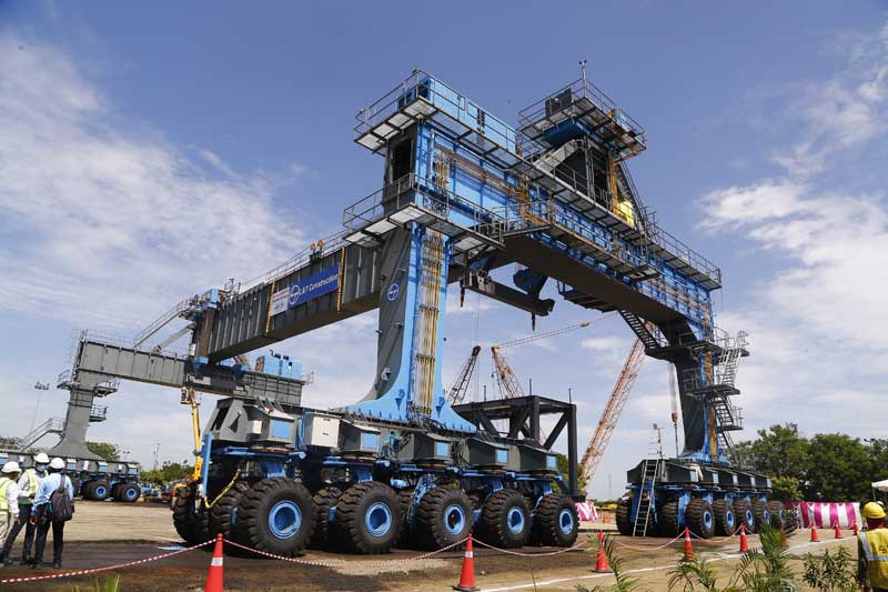
Straddle carriers
Straddle carriers can be utilized for the horizontal transportation of precast bridge deck segments. These segments are typically precast concrete or steel girders that need to be transported from the casting yard or staging area to the bridge construction site.The straddle carriers used for bridge deck erection may be modified or customized to accommodate the specific requirements of the bridge construction project.
Straddle carriers have a high lifting capacity, enabling them to handle heavy bridge deck components, such as precast concrete segments or steel girders. The lifting capacity can vary depending on the specific model and configuration of the straddle carrier.Latest models are equipped with long reach capabilities, which allow them to access the entire span of the bridge deck. This feature ensures that they can reach and lift segments from one end of the bridge to the other, facilitating efficient construction progress.
Straddle carriers come with advanced control systems that allow operators to precisely maneuver the equipment. They feature ergonomic control cabins equipped with multiple controls and displays for efficient operation. Additionally, safety systems such as load monitoring, collision detection, and stability control are often incorporated to enhance safety during bridge deck erection.
Movable scaffolding systems
Movable scaffolding systems, also known as self-launching or self-moving formwork systems, are commonly used in bridge deck erection. They allow for continuous construction, minimize the need for external cranes or lifting equipment, and provide a stable platform for workers to perform their tasks. The specific type and configuration of movable scaffolding equipment depend on factors such as the bridge design, span length, construction method, and project requirements. Here are some types of movable scaffolding equipment used for bridge deck erection:
1. Movable Formwork Carriages: Movable formwork carriages are self-propelled structures that move horizontally along the length of the bridge. They consist of a platform or deck supported by wheels or tracks, allowing for the controlled movement of the scaffolding system. These carriages typically incorporate formwork panels, working platforms, and safety features.
2. Hydraulic Push-Off Systems: Hydraulic push-off systems are used in conjunction with movable formwork carriages. They provide the pushing force required to move the formwork carriage to the next construction segment. Hydraulic cylinders or jacks are used to generate the required force for horizontal movement.
3. Adjustable Formwork Systems: Adjustable formwork systems allow for the adaptation of the scaffolding system to different bridge geometries. These systems often feature adjustable formwork panels and support frames that can be modified to match the specific shape and dimensions of the bridge deck.
Conclusion
Bridge deck erection is a crucial phase in bridge construction that involves the placement and assembly of structural elements to create the roadway or platform that spans across the bridge supports. By using the right equipment, adhering to safety protocols, and implementing efficient processes, bridge deck erection can be executed with precision and quality, leading to the successful construction of durable and reliable bridge structures.
Image Source: dlteng.com, everestengg.in, sigmahoist.com, liebherr.com, buildpedia.com

